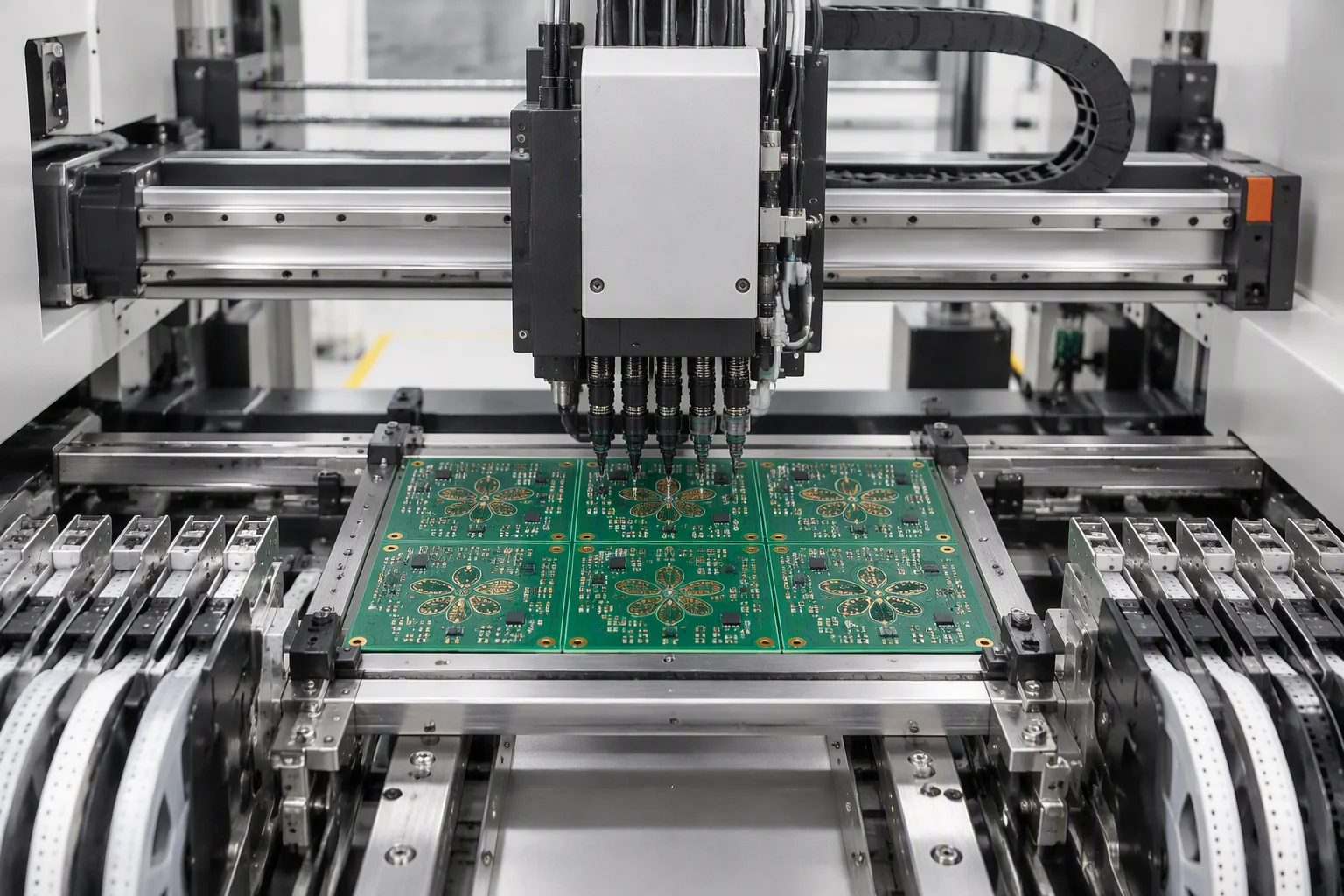
SMT placement
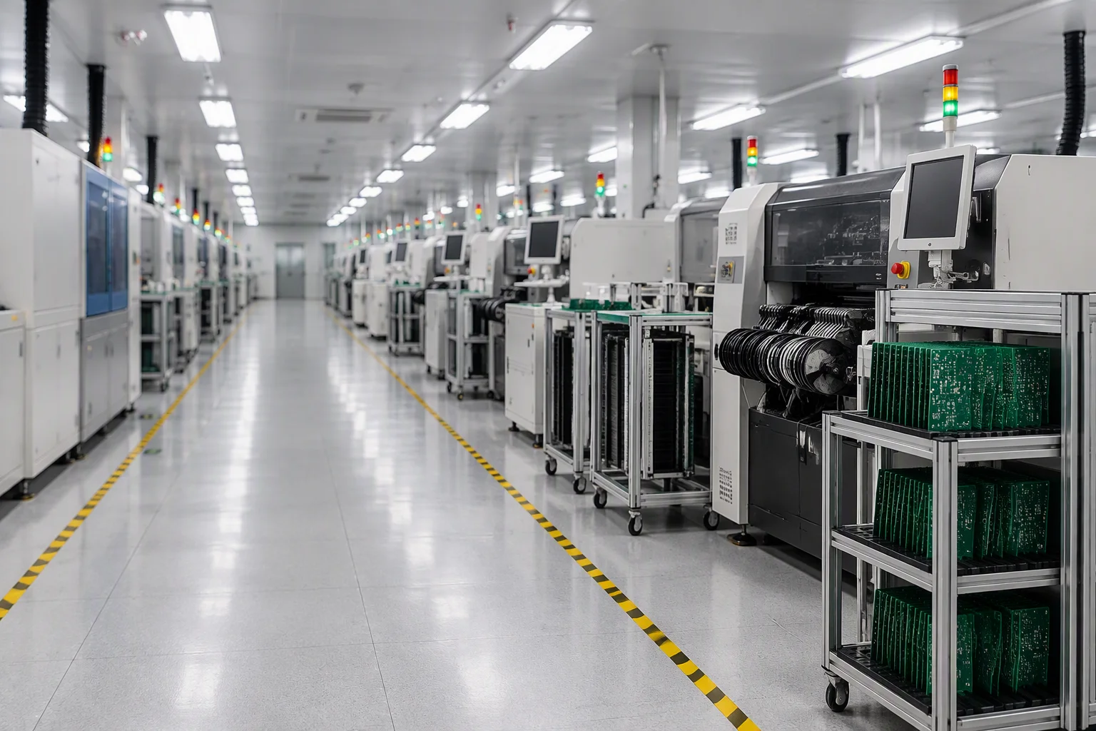
Stencil printing, 3D SPI, placement, reflow and 100% AOI across nine lines, down to 01005 chips and 0.25 mm-pitch BGA.
SMT assembly detail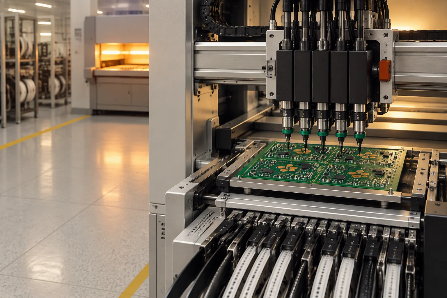
PCB assembly
Nine surface-mount lines and four to five through-hole lines feeding one inspection chain. 880,000 CPH of placement capability, ±25 µm accuracy, and every board passing 3D AOI before it leaves the floor.
Capacity & precision
Every figure below is a machine specification or a floor measurement you can hold us to in a purchase order. Placement rates are quoted as capability, never as a promised daily output.
| Parameter | Figure | Basis |
|---|---|---|
| Placement capability | 80,000 CPH | ASM SIPLACE X4iS, machine placement capability, not guaranteed throughput |
| Second placement platform | 72,000 CPH | Yamaha YSM20R, used for high-mix and changeover-heavy work |
| Placement precision | ±25 µm | Chip and IC placement across both platforms |
| Smallest chip | 01005 | 0201 also standard; µBGA, CSP and PoP in the same window |
| Finest package pitch | BGA to 0.25 mm | Fine pitch to 0.3 mm; QFP, QFN, LGA and CBGA supported |
| Component height | ≤25 mm SMT | Wave soldering accepts top 120 mm / bottom 15 mm |
| Lines and volume | 9 + 4–5 | Nine SMT and four to five DIP lines, 13,000 part numbers per month |
Four assembly services
Most boards pass through more than one of these four. Each card opens the page that carries the process detail, the equipment list and the acceptance criteria for that stage.
Stencil printing, 3D SPI, placement, reflow and 100% AOI across nine lines, down to 01005 chips and 0.25 mm-pitch BGA.
SMT assembly detail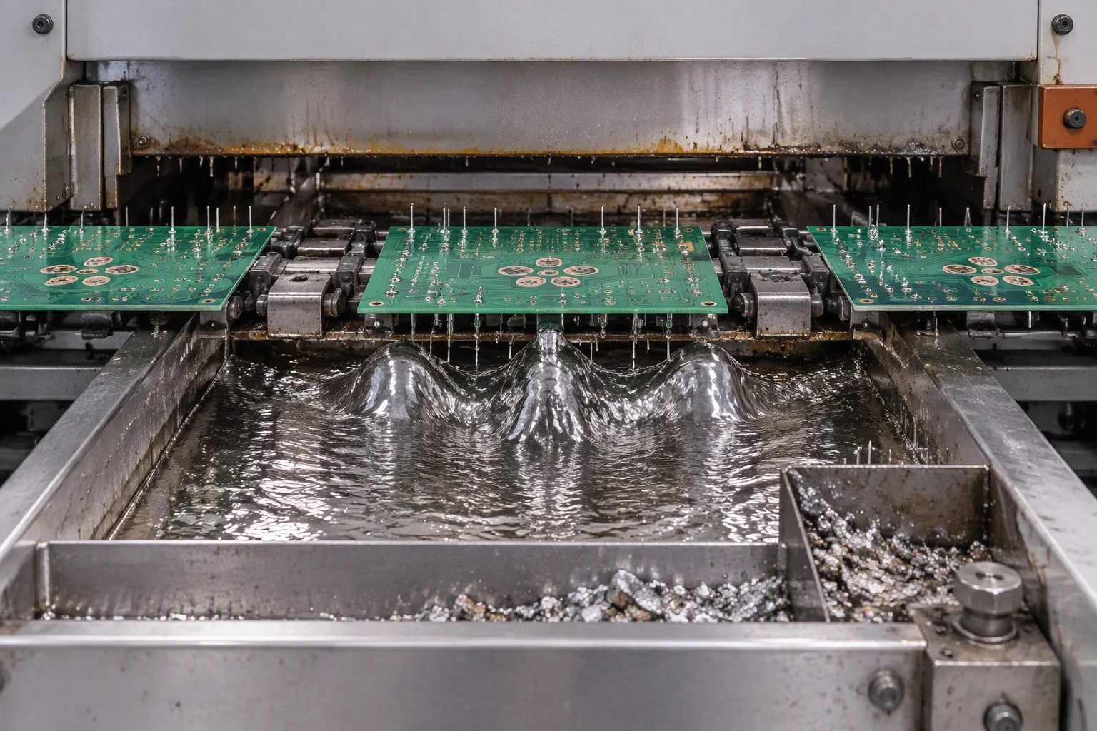
Wave soldering, programmable selective soldering, hand soldering and press-fit for mixed-technology boards with tall connectors.
Through-hole detail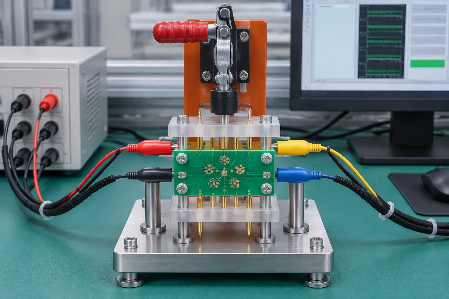
Flying probe, Agilent i3070 in-circuit test with 3,072 points, custom functional fixtures and X-ray on every batch.
Test & inspection detail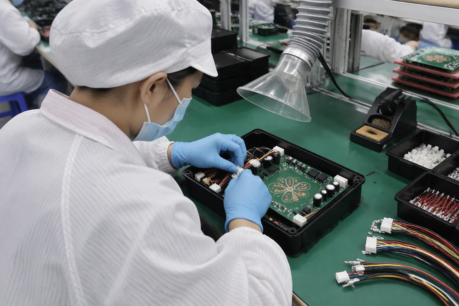
Component sourcing, conformal coating, potting, harnesses, sheet metal and final enclosure assembly, shipped as one build.
Turnkey detailAssembly flow
This is the whole route a mixed-technology board takes on our floor. Each node names the equipment that runs it and the figure that decides whether the board moves on.
Process boundary
Mixed-technology boards cross this boundary twice. Knowing which side a part belongs on is what keeps a quotation accurate: the two routes have different height limits, different solder methods and different inspection gates.
| Parameter | SMT, surface mount | THT, through-hole and wave |
|---|---|---|
| Components placed | 01005 and 0201 chips up to BGA at 0.25 mm pitch, QFN, LGA, CSP, PoP | Connectors, transformers, large electrolytics, relays, press-fit pins |
| Component height | ≤25 mm above the board surface | Top 120 mm / bottom 15 mm through the wave |
| Solder method | Reflow in 8–12 zones, lead-free peak 245–260 °C; leaded and lead-free both run | Wave soldering, programmable selective soldering, hand soldering, press-fit |
| Inspection gate | 3D SPI, then 3D AOI on 100% of boards across all nine lines | Visual criteria to IPC-A-610 Class 2 & 3 workmanship, soldering to J-STD-001 |
| Equipment | ASM SIPLACE X4iS at 80,000 CPH, Yamaha YSM20R at 72,000 CPH, ±25 µm | 4–5 DIP lines; Seho ECOSyS 3000 and ERSA Versaflow 3 for selective work |
| What drives the choice | Density, fine pitch and thermal mass small enough for reflow | Mechanical load, connector retention and heat that reflow cannot reach |
Incoming material & tooling
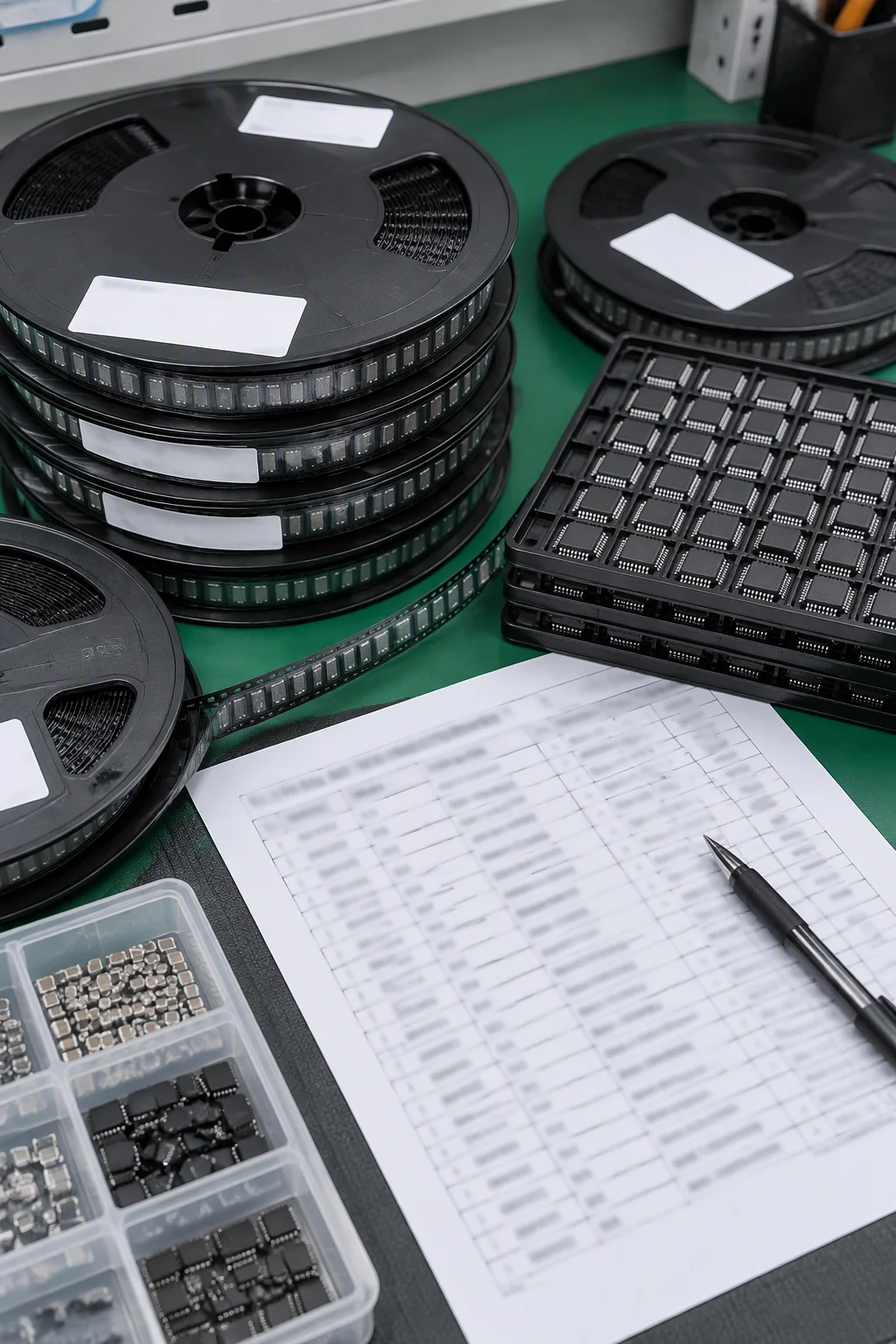
There is no repackaging charge hiding in the quotation. Reels, cut tape, tubes, trays, loose parts and bulk bags all load onto the same feeders, and the only files we need from you are a Gerber set, a BOM and a pick-and-place list.
Commercial terms
Assembly terms are the part of a quotation that decides whether a prototype programme is viable at all, so the five answers below are the ones buyers ask for first.
BOM review
Assembly risk usually arrives as a line item, not as a process fault. A buyer reviews every BOM by hand against a pool of more than 5,000 audited suppliers before a purchase order is raised, and flags what will not be there in time.
Quotation in 24 hours
Add the panelisation and any process requirement you already know. An engineer reviews the package and answers with a price, a lead time and the open questions, within 24 hours, no MOQ.
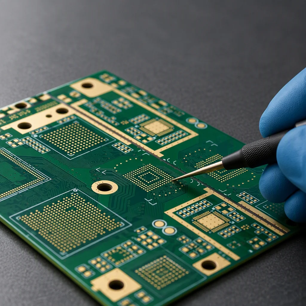
Send your Gerber, BOM or a plain description. An engineer, not a sales script, reviews it and replies within one working day. NDA on request.