Power boards where copper, creepage and heat are the design
Copper from 0.5 to 20 oz, aluminium IMS cores, 400–800 V DC
creepage planning and Class 3 documentation with a microsection per lot,
all inside one Shenzhen plant. Engineering review and quotation inside 24 hours.
In inverters, converters and battery racks a board failure is a
safety event, not a warranty claim. These are the three places a power design
goes wrong before it ever reaches the field.
01
100 A-class bus, 4–20 oz
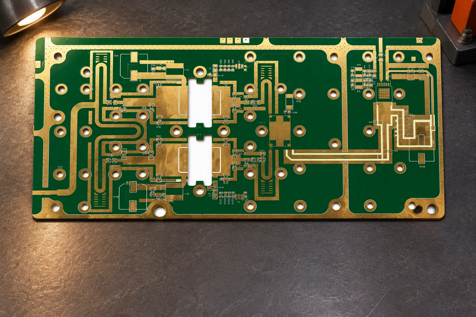
Copper weight is a thermal decision
A 100 A-class bus is not a trace-width sum. Copper weight, the via array
that carries the current between layers and the area available to dump heat
into the enclosure are one decision. Under-specify the copper and the board
still passes electrical test, then fails on temperature.
02
400 – 800 V DC isolation
The withstand test is where a layout fails
Above 400 V DC the build is set by creepage and clearance, the CTI grade
of the laminate and the geometry of the isolation barrier, not by the
schematic. Gaps drawn only on the surface layers, with the barrier broken on an
inner plane, are a routine cause of a failed dielectric withstand test.
03
Aluminium IMS, thermal cycling
The insulation layer is the weak link
On a metal-core build the dielectric between the copper and the aluminium base
carries the whole thermal and voltage load. Its grade, the copper weight on top
of it and the coating scheme have to be chosen together, or the assembly
delaminates across the thermal cycles the converter will actually see.
Requirement to process
What the design asks for, and how we build it
Heavy copper, metal cores and high-voltage isolation are quoted as
routine work here, not as engineering exceptions. The table below is the range we
hold in-house; anything outside it is answered at engineering review.
Power and energy storage builds, requirement and in-house answer
Requirement
How we build it
Copper weight
0.5 – 20 oz in-house. Power stages are specified at 4 – 20 oz; heavy copper starts at 3 oz = 105 µm and reaches 20 oz = 700 µm.
Metal-core and IMS
Aluminium-backed insulated metal substrate for LED drivers, gate-drive stages and any assembly that has to move heat straight into a heatsink.
Laminate
High-Tg FR-4 at Tg ≥ 170 °C as the floor for lead-free reflow and continuous thermal load; high-CTI grades (Material Group I (CTI ≥ 600)) for the isolation barrier.
Board thickness
0.4 – 3.2 mm, with the thicker end used where a barrier has to be held through the board rather than across the surface.
Maximum board size
600 × 1200 mm, which covers most inverter, converter and rack-control formats without splitting the panel.
Creepage and clearance
Partitioned routing and gap design to the limits in your safety file, held consistently across inner layers. We do not publish fixed millimetre values: the numbers come from the standard your product is certified to.
Impedance
±10% as standard and ±5% on premium builds, both verified by a TDR coupon at the board edge rather than by a calculation.
Fine features
2.5 mil line and space at the HDI grade, 6 mil (0.15 mm) as the cost-optimal production grade, 0.2 mm minimum mechanical drill, 0.15 mm minimum annular ring.
Schematic, not to scale, copper weight ladder from the in-house range
Environment protection
Coatings and pottings, applied selectively
Every assembly is cleaned ultrasonically and with DI water before
coating, and the coating is applied selectively to IPC-CC-830B so connectors,
test points, terminal blocks and press-fit holes stay solderable and serviceable.
Acrylic, 25–75 µm. General moisture and dust protection, and the easiest scheme to rework when a field repair has to happen.
Silicone, 50–210 µm. The widest service-temperature window of the four, chosen for boards that sit near a heatsink or cycle thermally.
Urethane, 25–75 µm. Solvent and chemical resistance with good adhesion, used where the assembly sees cleaning agents or fuel-cell chemistry.
Parylene, 5–50 µm. The thinnest coverage of the four, specified for high-impedance and high-voltage surfaces where mass and thickness matter.
Epoxy potting. Full encapsulation of a power stage, adding mechanical support under large electrolytics and transformers.
Polyurethane potting. Encapsulation with more flexibility, for assemblies that move slightly as they heat and cool in service.
Inspection chain
Ten gates between a panel and a shipped lot
The chain is the same for a 100-piece first production run and a
20,000-piece annual programme. Judgement criteria are named on every gate, so a
buyer can audit the record against the standard rather than against our word.
01 IQC
Bare boards and components inspected on receipt: dimensions, test coupon, date code, quantity, solderability.
02 3D SPI
Koh Young paste inspection on volume, area, height and alignment; out-of-tolerance prints trigger a wipe and reprint.
03 3D AOI
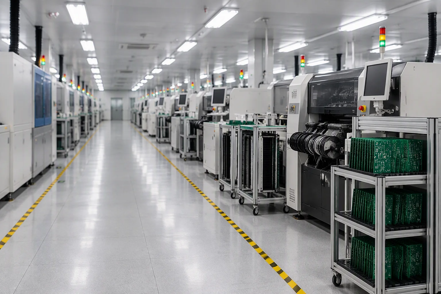
Omron VT-RNS and SAKI BF-18D on 100% of boards, on every SMT line: missing parts, polarity, offset, tombstoning, joint quality.
04 Digital X-ray
Nordson DAGE XD7600NT on hidden joints, a minimum of 5 pieces per lot, judged to J-STD-001 for voiding and bridging.
05 Flying probe
Takaya APT-1500F with four heads, fixture-free, so a first article is electrically verified without waiting for a bed-of-nails.
06 ICT
Agilent i3070 with up to 3,072 test points: opens, shorts, passive values, diode orientation, IC continuity, per-board pass or fail on file.
07 FCT
A fixture built for the product simulates the real load: power-up, signal integrity, firmware programming, system-level behaviour.
08 FVI
Final visual inspection to IPC-A-610 Class 2 or Class 3 as ordered, with an inspector stamp, serial number where required, and photographs.
09 OQC
Outgoing check on packaging, labelling, quantity and documents, sampled to AQL ANSI/ASQ Z1.4 (general inspection level II, single sampling, normal severity, AQL 0.65 for major defects) before the carton is sealed.
10 Traceability
Per-board serialisation, photograph archive and material certificates shipped with the lot; monthly quality review with 8D/CAPA.
Inspection frequency by record type, per board, per lot, per shipment
Compliance on both sides
Our credentials, and the standards your submission cites
Two different lists get confused in this industry. The first row is
what the plant holds. The second row is the standards our build class and
documentation package are written against so that your certification body sees a
consistent file, the listings themselves belong to your product.
ISO 9001:2015 certifiedUL 796 recognisedRoHS & REACH compliantIPC-6012 Class 3environmental management practices (not certified to ISO 14001)
Quality system certified to ISO 9001:2015 and audited annually by SGS. High-voltage builds are held to IPC-6012 Class 3 documentation: per-lot microsection, thermal stress, ionic cleanliness at or below 1.56 µg/cm² NaCl equivalent, and material lot traceability.
UL 796
Recognised printed wiring board manufacturing, held with UL
for the fabrication process, so your end product can carry a UL component
recognition.
RoHS & REACH
Compliant lead-free lines. Declarations of conformity come
from the laminate and component suppliers, and a per-board material declaration
report ships with the lot.
Class 3 documentation
Per-lot microsection and thermal stress results, ionic
cleanliness at or below 1.56 µg/cm² NaCl equivalent, and material
lot traceability held against the board serial number.
Full scanned certificate package released on request.
Application case
Converter and storage-control boards
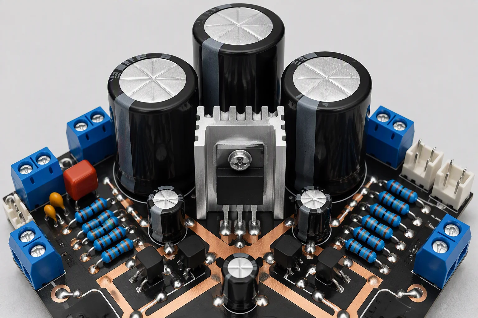
The project type we see most in this industry: a push-pull or
SEPIC-class topology board with a bulk-capacitor bank, a heatsink footprint and a
metal-core sister board on the same order.
Requirement. The power stage needed 4 oz copper on the switch node, a large copper area to spread heat under the amplifier devices, and a coating that would survive condensation without covering the terminal blocks.
Solution. Copper was partitioned by current path rather than by net class, thermal vias were arrayed under the dissipating devices, the aluminium IMS board was processed on the metal-core line, and selective coating masked every connector and test point.
Outcome. 100% AOI coverage, X-ray on a minimum of 5 pieces per lot, functional test on a fixture built for the product, and OQC sampled to AQL ANSI/ASQ Z1.4 (general inspection level II, single sampling, normal severity, AQL 0.65 for major defects) with the coating record filed per lot.
Send the Gerber with the copper weight and current.
Tell us the voltage class, the continuous current on the main
paths and the safety standard the product is certified to. First production of
100–500 pieces and series of 2,000–20,000 a year run on the same
lines.