Wearables
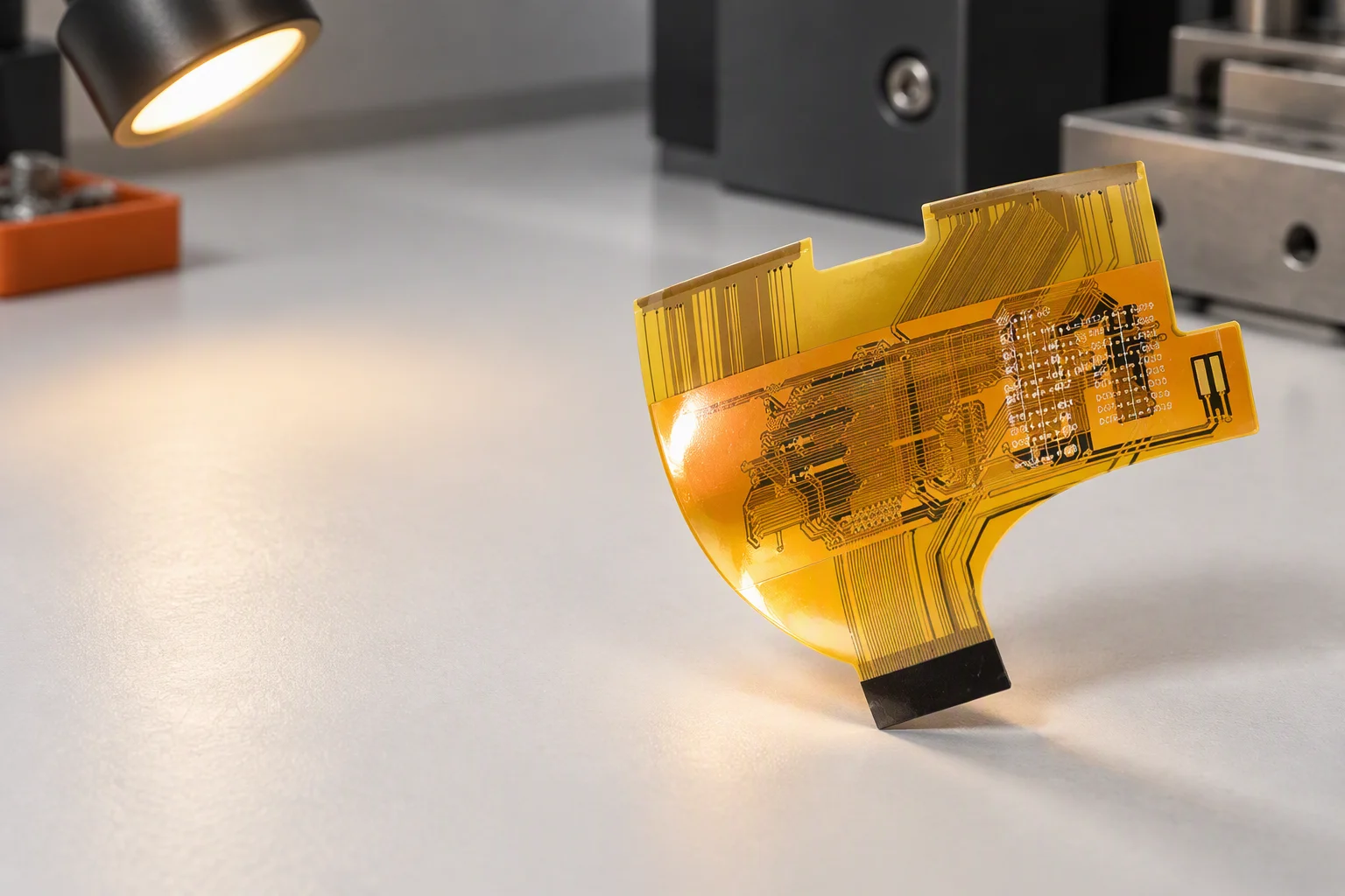
Thin adhesiveless polyimide that fits inside a wristband, copper from 0.5 oz and stiffened pads for the sensor and antenna connections.
Flex & rigid-flex
Single-sided and multilayer FPC plus rigid-flex built on polyimide film, with coverlay, adhesive or adhesiveless laminates and stiffeners in FR-4, polyimide or aluminium. Copper starts at 0.5 oz, finishes run from ENIG to OSP, and the same plant laminates rigid boards to 58 layers.
Adhesive or adhesiveless
A flex laminate is a copper foil, a polyimide film and something in between. That something decides the achievable bend behaviour, the finished thickness and how the circuit survives reflow, so it is settled before the stackup is drawn.
| Dimension | Adhesive construction | Adhesiveless construction |
|---|---|---|
| Dielectric structure | Polyimide film bonded to copper foil with an acrylic or epoxy adhesive layer on each side | Copper cast or sputtered directly onto the polyimide film, with no separate adhesive layer |
| Cover layer | Coverlay, a polyimide film pre-coated with adhesive, laminated over the finished traces | Coverlay or photo-imageable solder mask, depending on the pad density and the bend radius required |
| Bend behaviour | Suits static bends and assemblies that are folded once and fixed in place | Preferred where the circuit flexes repeatedly in service; the requirement is confirmed per project against the stackup and stiffener plan |
| Finished thickness | Thicker for the same copper weight, because the adhesive adds to the build | Thinner for the same copper weight, which matters inside a wearable or a camera module |
| Copper weight | From 0.5 oz, which remains the practical starting point on both constructions | From 0.5 oz, with fine-line etching on thin foils for dense pad fields |
| Typical use | Ribbon connections, static folds, cost-sensitive consumer assemblies | Wearables, medical catheters and probes, camera modules, high-cycle hinge joints |
How a flex circuit is built
Two stages here have no equivalent on a rigid line: the coverlay press, which replaces solder mask as the mechanical cover, and stiffener bonding, which is what makes a flexible circuit solderable on an SMT line.
Polyimide laminate cut to panel size, with the adhesive or adhesiveless construction fixed on the released stackup.
Punched or drilled vias and registration holes; flexible cores are handled on carriers to stop the thin film stretching.
Dry film, exposure and etching of the copper traces, starting from 0.5 oz foil.
Coverlay pressed over the traces with openings for the pads, giving the circuit its mechanical and environmental cover.
ENIG, immersion tin or OSP, chosen against the assembly process and the connector mating requirement.
FR-4, polyimide or aluminium stiffeners bonded where connectors, fine-pitch parts and mounting holes need a rigid base.
Laser cutting or die cutting of the outline, with the breakaway tabs and carriers that hold the part through SMT.
Continuity and isolation test on the flexible panel, with impedance coupons where a controlled-impedance flex is specified.
What holds the bend
A flexible circuit only behaves predictably where the neutral axis is controlled. These four elements are how that is done, and each one is specified on the drawing rather than left to the shop floor.
Rigid-flex in detail
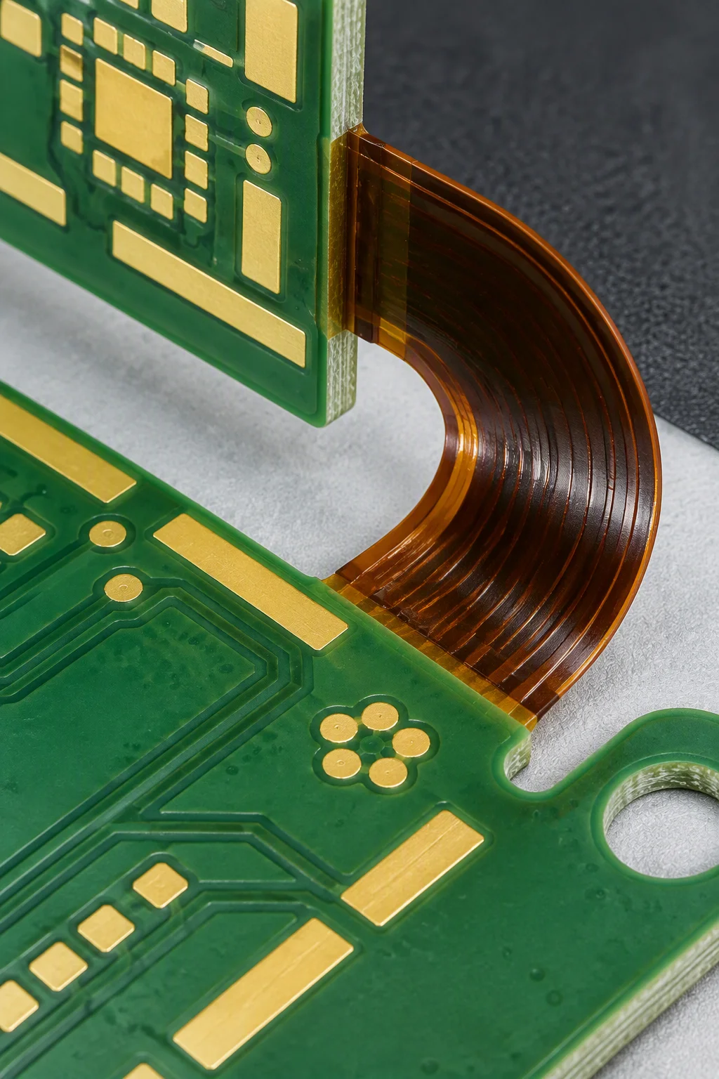
Everything either side of the transition zone is ordinary rigid and ordinary flexible work. The bonded band between them is not, and it is the first thing an engineer looks at when a rigid-flex drawing arrives.
Where flex pays for itself
The same polyimide process serves all four sectors, but the constraint that decides the build is different in each one.
Thin adhesiveless polyimide that fits inside a wristband, copper from 0.5 oz and stiffened pads for the sensor and antenna connections.
Medical-grade process capability with serialisation and full traceability, ionic cleanliness to 1.56 µg/cm² and parylene or polyurethane coating above 500 MΩ for probe and catheter assemblies.
Automotive-grade process capability with PPAP and IMDS documentation where the harness runs into a moving axis: multilayer rigid-flex, Tg ≥170 °C laminate and −55/+125 °C for 1,000 cycles.
Rogers and Taconic laminates with impedance held to ±10% standard and ±5% on premium builds, verified by TDR coupons on the panel border.
Flex capability window
Flexible work is quoted from the drawing rather than from a table, because the bend and the stiffener plan change the process. The rows below are the inputs the review works from.
| Item | Window | How it is confirmed |
|---|---|---|
| Layer count | Reviewed per stackup | The rigid and flexible sections are counted separately on the drawing; the rigid side draws on the same 1–58 layer lamination process |
| Copper weight | from 0.5 oz | Chosen with the line width and the bend requirement, since heavier copper stiffens the flex tail |
| Stiffener material | FR-4, polyimide or aluminium | Selected from the connector type, the heat load and the space inside the enclosure |
| Panelisation & carriers | With breakaway tabs and tooling strips | Array layout and carrier design agreed so the flexible panel can run across a 510 × 460 mm conveyor envelope |
| Surface finish | ENIG, immersion tin or OSP | Matched to the mating cycles on gold fingers or the solderability window on the assembly side |
| Electrical test | Continuity and isolation on every panel | Flying probe or fixture test, with an impedance coupon read where controlled impedance is specified |
| Bend requirement | Confirmed per project | Static or dynamic, the intended bend radius and the stiffener positions are fixed at DFM review against the released stackup |
Flex parts in production
Four representative parts, all built on the eight-stage flow above: a straight ribbon, an irregular profiled circuit, a rigid-flex array and a stiffened edge-connector module.
Parallel traces on polyimide with gold contact fingers at one end and a stiffener patch behind them for the connector.
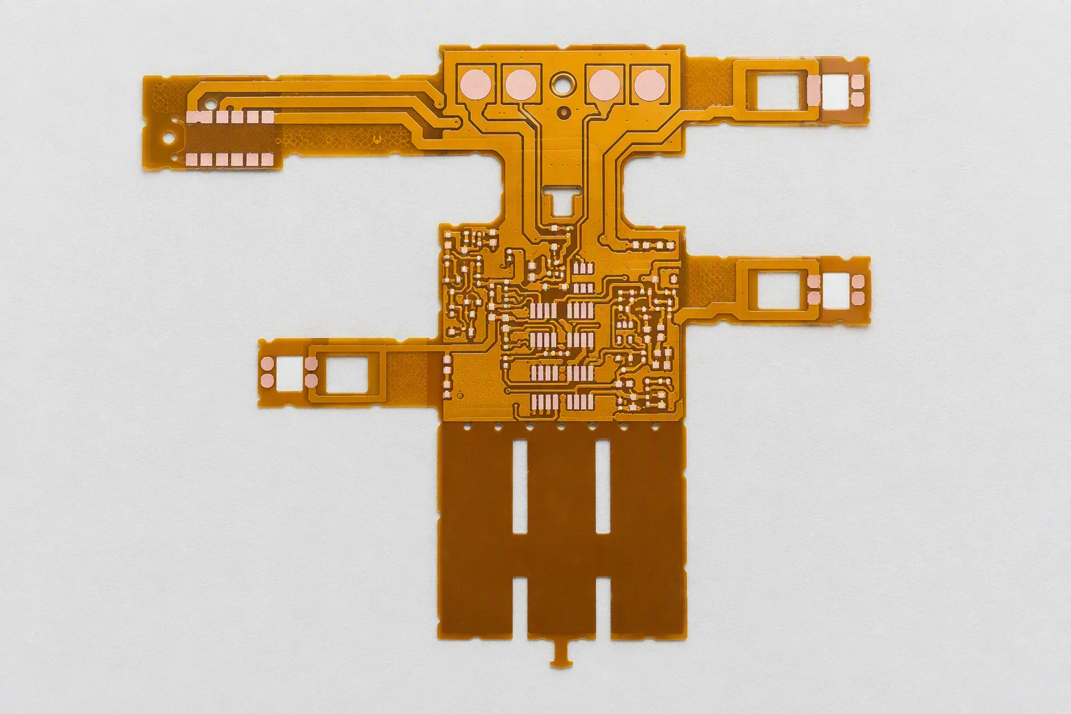
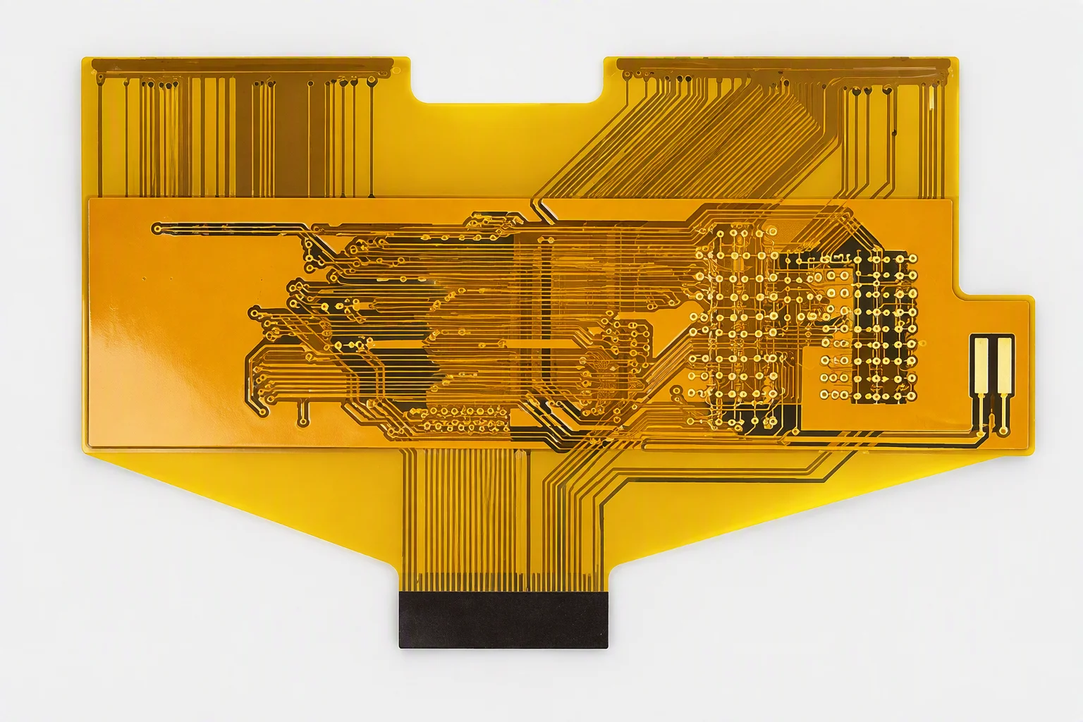
Routed to the enclosure rather than to a rectangle, so the circuit follows the available space instead of consuming it.
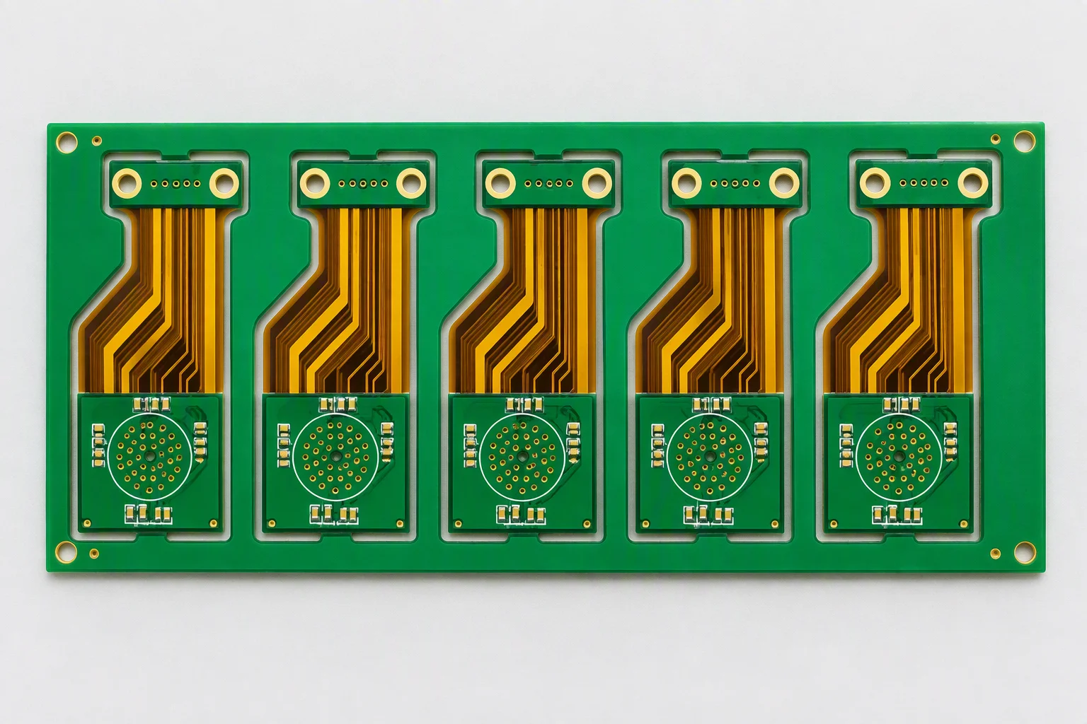
Five rigid islands joined by polyimide bridges on one panel, with routed tabs and tooling strips for the SMT line.
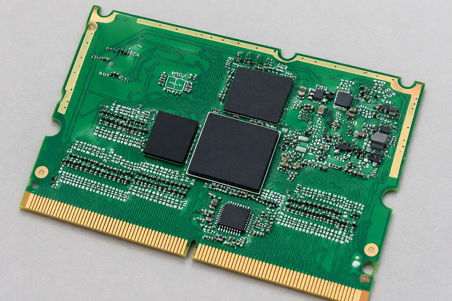
Hard-gold fingers at 150–200 HK25 on a stiffened edge, rated above 10,000 mating cycles; the bevel angle follows the connector's insertion count and is confirmed at engineering review.
Quotation in 24 hours
Mark where the circuit bends, whether it bends once or repeatedly, and where the stiffeners have to sit. An engineer confirms the construction and returns both lead-time brackets within one working day. NDA on request.
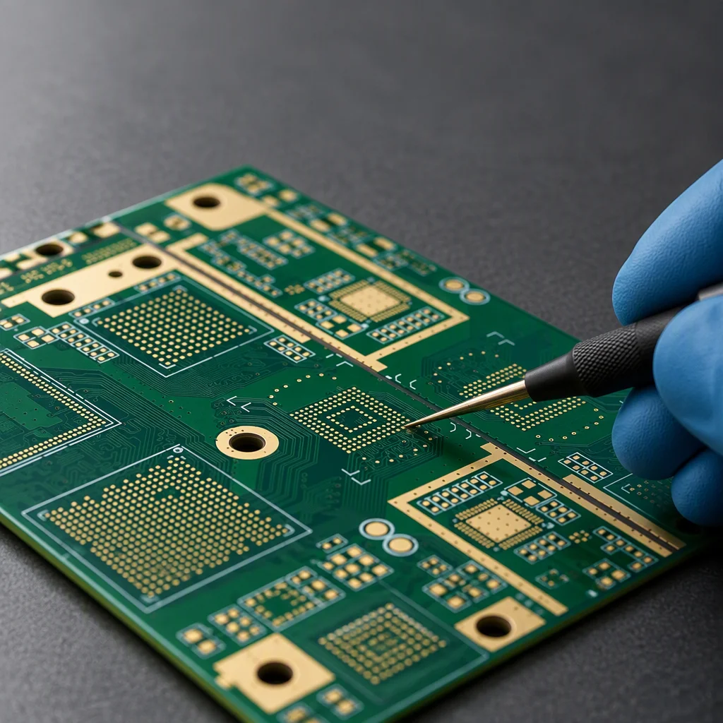
Send your Gerber, BOM or a plain description. An engineer, not a sales script, reviews it and replies within one working day. NDA on request.