IoT & wireless devices

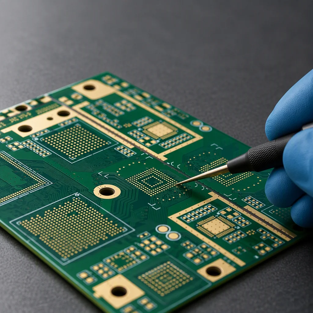
RF boards are laid out to impedance, not to habit

A 2.4 GHz trace is not a digital trace with a different name. Antenna keep-out, an unbroken reference plane, 50 Ω single-ended and 100 Ω differential routing, and 15–20 mm between the radio and the digital section decide whether your module passes certification in weeks or in months.

±5 % impedance, TDR-verified 0.1 mm laser microvia 2.5 mil line / space
Laminate & finish options

Where wireless projects stall

Three failures that never show up on a continuity test

A wireless board can pass every electrical check we run and still fail its certification, its range test or its unit economics. These are the three we plan against.

Pain 01 · layout

The keep-out that quietly filled up

An antenna clearance zone is the first casualty of a late change: a battery, a shield can or a ground pour drifts into it, and 2.4 GHz efficiency drops with nothing failing a continuity or an in-circuit test. The same applies to a reference plane broken by a via field or a connector cut-out. Both are cheap to catch at DFM review and expensive once the enclosure is tooled and the certification booking is paid for.
Pain 02 · certification

Certification is the schedule risk, not the board

With a pre-certified module and a clean RF section, EU RED 2014/53/EU runs in four to six weeks. Design your own radio, or fail the first pass, and the same program takes three to six months with retest budget attached. Since 1 August 2025 Article 3.3 adds EN 18031 cybersecurity evidence to that queue, and the security element you choose lands in the BOM.

Pain 03 · volume

Fifty pieces priced like a thousand

Early wireless products ship in tens, not thousands: a pilot build of 50 units, a revision, then 500 while the design settles. Minimum order quantities, tooling charges and setup fees turn each iteration into a budget decision, which is why assembly from a single board matters more here than a fraction of a cent on placement cost.

RF requirement → process answer

The requirements that decide whether the radio works

These are the lines a reviewer checks first on a wireless board. Each one is answered with a stackup decision, a layout rule or a measurement, not with an adjective.

RF section layout, antenna keep-out free of copper, a 50 Ω single-ended feed on Rogers-class laminate with a continuous reference plane, and 15–20 mm of separation between the radio section and digital routing Antenna keep-out no copper, no pour no components 50 Ω single-ended feed width set by the stackup Rogers RO4350B, Dk 3.48 ENIG finish for flatness ±5 % with a TDR coupon per lot 15–20 mm RF-to-digital separation digital section kept out of the RF zone continuous reference plane under the RF trace, no splits
Wireless requirements and how the board is built to meet them
RF requirement Process answer How it is proven
50 Ω single-ended trace Trace width and dielectric taken from the released stackup; ENIG finish (Ni 3–6 µm + Au 0.05–0.1 µm) for flatness at the feed point TDR coupon on the board edge, measured and reported with every lot
100 Ω differential pair Pair geometry set by the laminate; Rogers RO4350B at Dk 3.48 (specified as an absolute tolerance by the laminate supplier) instead of FR-4 at Dk 4.2–4.8 TDR coupon; differential impedance target held to 100 Ω
Impedance tolerance ±10 % standard, ±5 % on premium builds, with the solder-mask shift of 2–5 Ω inside the coupon budget Per-lot TDR measurement; data shipped with the boards
Reference plane continuity No plane splits under RF traces; stitching vias along the trace edges; ground pour kept away from the antenna zone Layout review gate before fabrication release
Antenna keep-out Keep-out held exactly as drawn. No copper, no components, no mask dams, no shield can intrusion DFM report flags any part or pour placed inside the keep-out
RF-to-digital separation 15–20 mm between the radio section and digital routing; shield-can footprint reserved on the first revision Reviewed at DFM and confirmed on the first article

Placement capability

Small parts, tight pitches, one inspection gate

A wireless board is usually the densest board in the product, and the radio module is rarely the smallest part on it. These are the placement limits we work inside.

  • 01005 and 0201 passives, from reel, cut tape, tube, tray or loose parts
  • BGA to 0.25 mm pitch, including µBGA, CBGA, CSP and PoP stacks
  • QFN, QFP and LGA with fine pitch to 0.3 mm, plus module shield cans and connectors
  • SMT component height to 25 mm, so a module or an inductor does not force a second process
  • Placement accuracy ±25 µm on ASM SIPLACE X4iS and Yamaha YSM20R lines
  • 3D SPI paste measurement, then 3D AOI on 100 % of boards; X-ray on a minimum of 5 boards per lot

Single-line placement capability is 80,000 CPH on the ASM SIPLACE X4iS and 72,000 CPH on the Yamaha YSM20R; the throughput a program actually sees depends on board mix, component count and panel configuration, so we quote cycle time from your BOM rather than from a nameplate figure.

Volume

One board, five hundred, ten thousand, the same line

Prototypes and series production run on the same nine SMT lines, through the same AOI gate. That is what makes a pilot build representative instead of a laboratory exercise.

  • No MOQ. An order can start at a single board and repeat at any quantity
  • Pilot runs of 1–500 boards and series volumes above 10,000 a year on the same equipment
  • Engineering review and quotation within 24 hours; free DFM check before the PO
  • PCBA lead time typically 10–15 days with parts in stock, 5–7 days expedited
SMT assembly detail
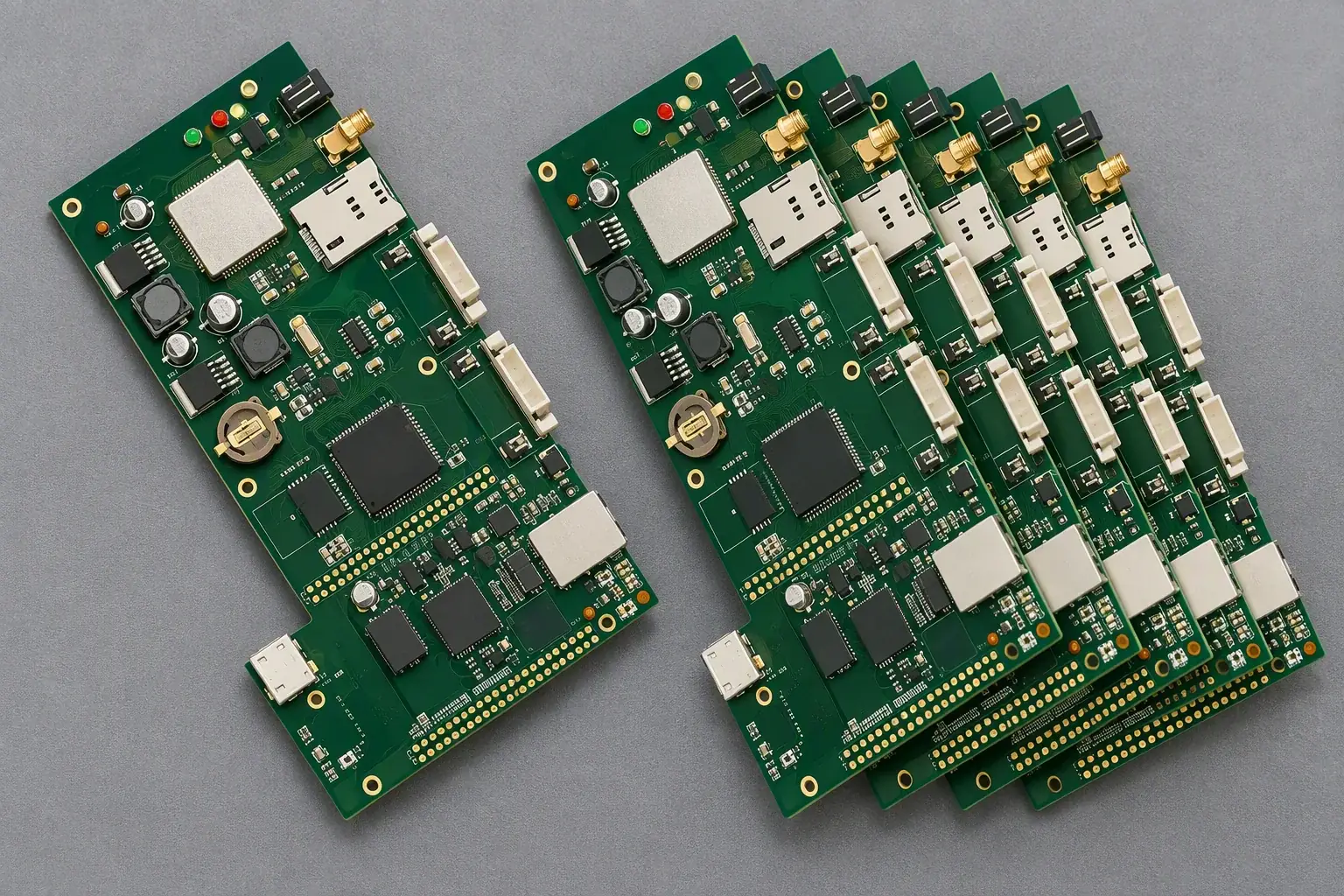
Wireless development board centred on a bench with a single prototype unit beside a short production run of the same board

Compliance

The plant's certificates, and your radio certificate

Two different things, and buyers are right to separate them. Radio approval belongs to your product; ours is to keep the RF section inside the reference design so the submission tests what was simulated.

ISO 9001:2015 certified UL 796 recognised RoHS & REACH compliant IPC-A-610 Class 2 & 3 workmanship ANSI/ESD S20.20 handling

ISO 9001:2015

Quality system certified to ISO 9001:2015, audited annually by SGS. Radio builds add impedance verification: 50 Ω single-ended and 100 Ω differential confirmed by TDR coupon on the panel border, so a certified module still sees the line it was tested against.

UL 796

Recognised printed wiring board fabrication, the route by which a wireless product reaches its own UL listing.

RoHS & REACH

Compliant lead-free assembly with material declarations available per board, so your technical file is complete before the notified body asks.

Inspection grade

Class 2 is the right grade for this vertical: it is sufficient for module-based wireless products, and Class 3 would add cost and days without adding radio performance.

Full scanned certificate package released on request.

Application case

A four-element antenna array with GPS and an SD socket

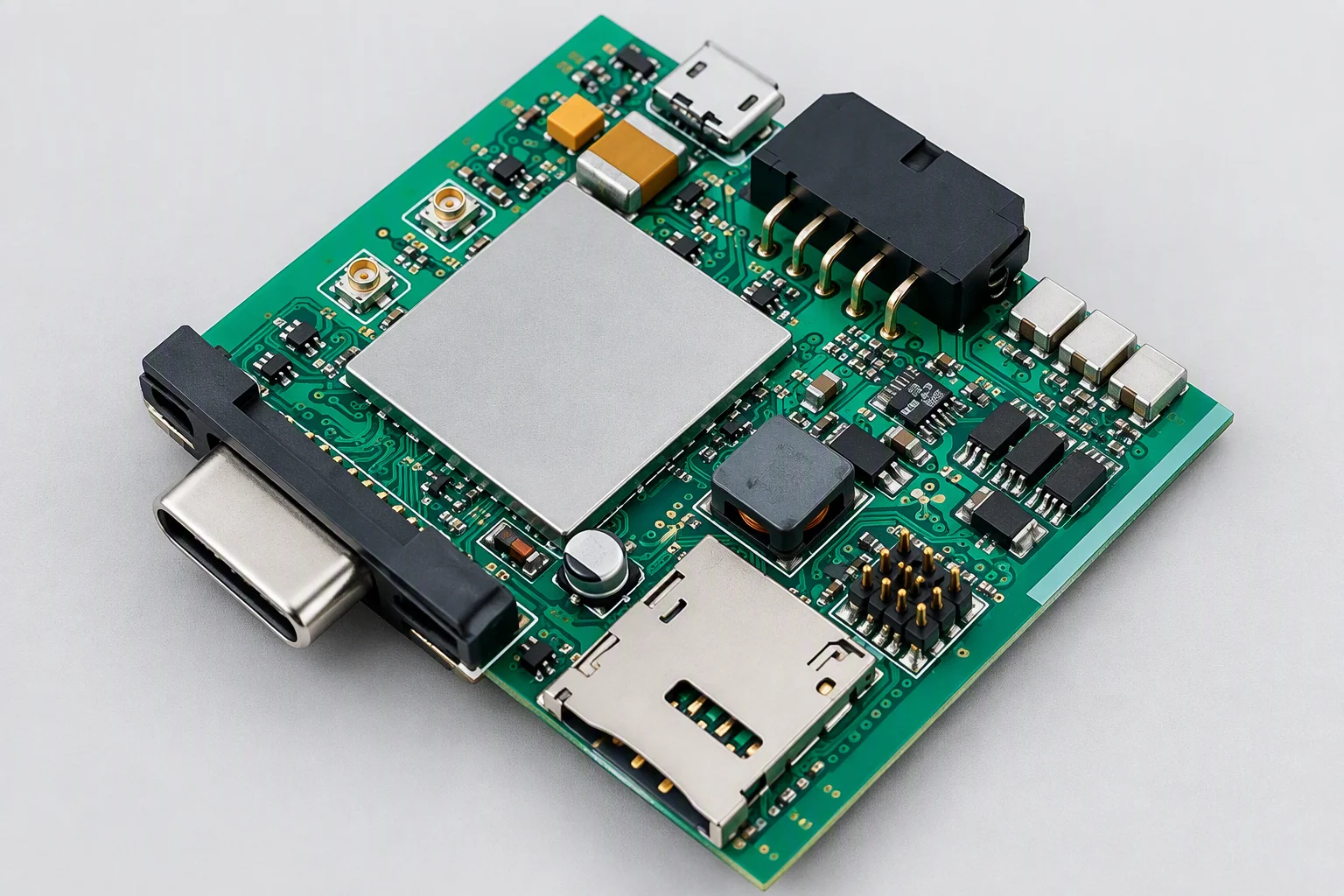
A wireless communication module board built as a project type: a four-element microstrip antenna array, a GPS receiver and an SD-card socket on one stack, with the antenna zone cleared to the customer's keep-out drawing and the shield-can footprint reserved over the radio before the first panel was released.

  • Stackup: 4 layers, Rogers-class laminate under the RF section, FR-4 for the digital side
  • Impedance: ±5 % on premium builds, verified with a TDR coupon on every lot
  • Assembly: 0.25 mm pitch BGA, module shield can, fine-pitch connector placement
  • Function: a custom FCT fixture exercises the GPS and SD interfaces on every board
  • Outcome: 3D AOI on 100 % of boards, X-ray on a minimum of 5 boards per lot, carton sampled to AQL ANSI/ASQ Z1.4 (general inspection level II, single sampling, normal severity, AQL 0.65 for major defects)
Positioning module board in three-quarter view with its card socket and antenna zone facing the camera
SMT assembly hall aisle with placement machines, feeder carts and green PCB panels stacked on a trolley at the Saturn PCBA plant

Quotation in 24 hours

Send the stackup target and the antenna keep-out

Gerber, BOM, pick-and-place and your keep-out drawing. Tell us whether you are reusing a certified module or designing the radio, and we will review the RF section, quote a price and return a DFM report within one working day.

[email protected]
Quote in 24 h