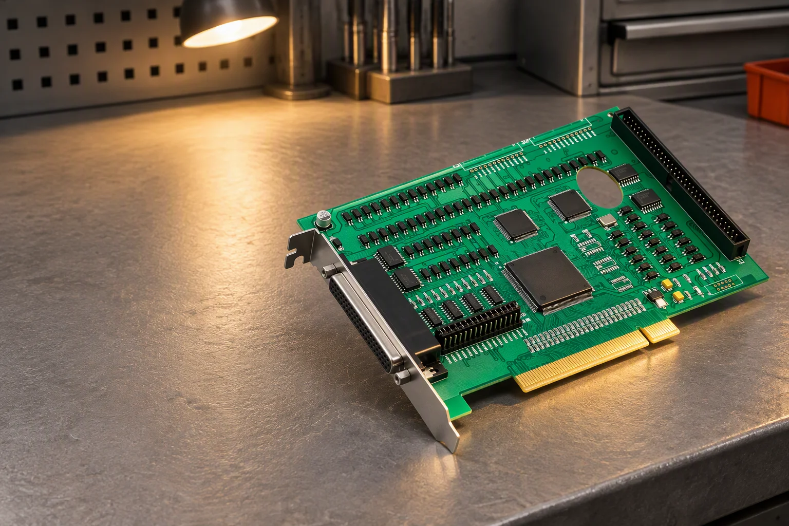
Industrial control card angled low so its gold-finger edge connector and isolation slot catch the light, photographed on an ESD bench

Industrial control & automation

Boards for machines that must run for 10–15 years

Industrial control is not consumer electronics at a higher price. It is a supply commitment measured in years, a −40 … +85 °C duty envelope, a 24 V I/O boundary that has to stay isolated while drives switch next to it, and a paper trail that still makes sense when the machine is serviced in year nine.

Building in Shenzhen since 1998 Board thickness 0.4–3.2 mm Copper to 20 oz Tg 170–180 °C laminate
See the inspection chain

What breaks industrial programs

Three ways a controller board fails after it is approved

None of them shows up on the first article. They appear in year three, on a cold morning, or when purchasing tries to repeat last year's order.

Pain 01 · availability

A part that goes end-of-life ten years too early

Buyers re-order the same board for five to ten years and expect it to stay manufacturable for the full 10–15 year machine life. One discontinued MCU or a single-source DC/DC converter forces a re-spin, a fresh DFM round and, when the board sits inside a certified machine, requalification of the whole assembly. Sourcing discipline and last-time-buy planning are what prevent it, not a faster layout team.
Pain 02 · environment

−40 °C at the panel door, +85 °C inside the cabinet

The duty envelope starts at −40 … +85 °C, and extended builds are specified to +105 °C, which is why industrial designs move to Tg 170–180 °C laminate instead of the standard 130–140 °C material and accept the 1.2–1.5× material cost. Add vibration from contactors and drives, and every marginal solder joint on a 25 mm-tall electrolytic or transformer becomes a field failure.

Pain 03 · isolation & EMI

24 V field wiring sharing a board with a switching supply

Isolated 24 V inputs, relay drivers, an RS-485 port and a switching regulator live on one PCB, so creepage, galvanic separation and return-path discipline matter more than trace density. CISPR 11 / EN 55011 emissions are proven at system level, but the layout, the ground partitioning and the conformal coating either help that test pass or make the fix an expensive re-spin.

Requirement → response

Every pain point has a parameter behind it

The numbers below are in-house ranges, not aspirations: each row is what we laminate, drill, plate or coat, and how the result is measured before the board leaves.

Six-layer industrial control stackup, signal and ground layers around a 2 oz inner power layer on High-Tg 170–180 °C laminate, 0.4–3.2 mm finished thickness, impedance held to ±10 % and verified on a board-edge TDR coupon 0.4–3.2 mm L1 · signal · 1 oz L2 · ground plane L3 · power · 2 oz L4 · signal · 1 oz L5 · ground plane L6 · signal · 1 oz High-Tg laminate Tg 170–180 °C reflow peak 245–260 °C 2 oz inner copper field-side current path Impedance ±10 % TDR coupon per lot
Industrial control requirements and the in-house response behind each one
Requirement In-house response How it is verified
Wide-temperature duty High-Tg FR-4 at Tg 170–180 °C; lead-free reflow peak 245–260 °C Laminate certificate per lot; thermal stress 288 °C solder float for 10 s
Mechanical envelope Finished thickness 0.4–3.2 mm; panels to 600 × 1200 mm First-article report with measured stackup and drilled thickness
Power and current paths Copper 0.5–20 oz; heavy copper from 3 oz (105 µm), 2–6 oz typical for I/O and drive rails Cross-section microsection taken from the qualification lot
Controlled impedance ±10 % standard, ±5 % on premium builds; differential pairs to 100 Ω Board-edge TDR coupon measured and reported per lot
Mixed-technology assembly SMT components to 25 mm high; wave and selective soldering for through-hole 3D AOI on 100 % of boards; X-ray on a minimum of 5 boards per lot to J-STD-001
Inspection grade IPC-A-610 Class 2 as standard, Class 3 documentation on request Final visual inspection with inspection stamp, serial number and photo record
Condensation and corrosion Conformal coating to IPC-CC-830B: acrylic 25–75 µm, silicone 50–210 µm, polyurethane 25–75 µm, parylene 5–50 µm Coating coverage and thickness check; selective-coating mask reviewed before spray

Supply continuity

A BOM is a ten-year commitment

Long-life programs rarely fail on layout. They fail on availability: in 2026 standard FR-4 laminate is quoted at 6–8 weeks, MLCCs at 20–50+ weeks, and automotive-grade MCUs and FPGAs beyond 52 weeks. We treat the BOM as a living document for the life of the product.

  • 5,000+ certified suppliers, authorised distribution by default; no broker or spot-market parts without your written approval
  • Lifecycle watch on every line item, with alternates and last-time-buy recommendations raised before an end-of-life notice arrives
  • Deviation and substitution control in writing, traced to date code and lot on the shipping documents
  • Re-orders from one board, no MOQ, and the same inspection grade as the first article
Turnkey sourcing & BOM management
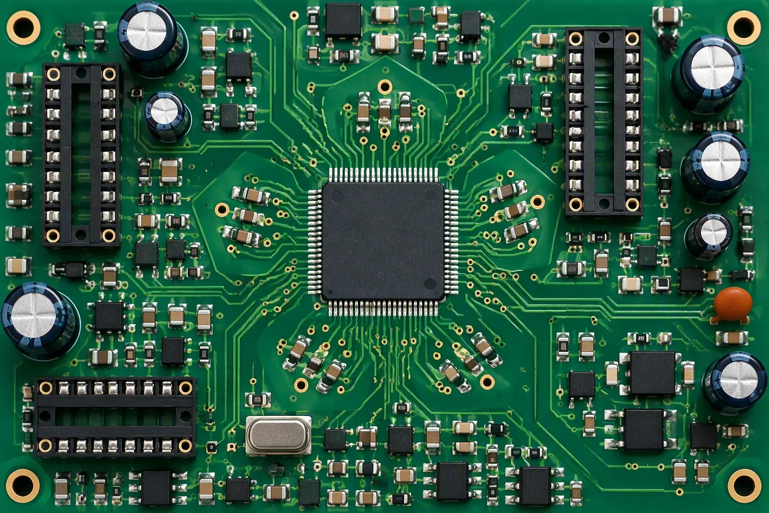
Close view of a long-life industrial control board showing its long-life components and a marked alternative footprint

Evidence per lot

What a control board carries out of the door

Ten stations, one traveller. Each one either measures something or records something, stations that do neither do not exist here.

Incoming

Bare-board dimensions and coupon check; component date codes recorded against the BOM revision.

Paste print

Koh Young 3D SPI measures volume, area, height and alignment; a failing print is wiped and reprinted automatically.

Placement

Every board on all nine SMT lines passes 3D AOI for presence, polarity, offset and joint shape.

Hidden joints

Nordson DAGE X-ray on a minimum of five boards per lot; voiding judged to J-STD-001, images archived.

Net test

Takaya flying probe with four heads proves continuity and isolation before any fixture is built.

In-circuit

Agilent i3070 exercises 3,072 test points and writes a pass/fail record against each board.

Function

A fixture built for the product powers the board, loads firmware and drives the I/O the machine actually uses.

Final visual

IPC-A-610 Class 2 or Class 3 inspection, inspection stamp, serial number where the program calls for it.

Shipment

Carton, label and document check to AQL ANSI/ASQ Z1.4 (general inspection level II, single sampling, normal severity, AQL 0.65 for major defects); CoC and test records travel with the goods.

Field feedback

Returns are matched to their own AOI, X-ray and test records, then closed with an 8D/CAPA action.

Certification & compliance

What we hold, and how the codes are worded

Industrial programs are audited on precision of language as much as on process, so the status of each item is stated exactly as it stands.

ISO 9001:2015 certified UL 796 recognised UL 94 V-0 via UL 796 IPC-A-600 / IPC-6012 IPC-A-610 Class 2 & 3 workmanship CISPR 11 / EN 55011 support RoHS & REACH compliant

ISO 9001:2015

Quality system certified to ISO 9001:2015, audited annually by SGS. Industrial builds add the checks this vertical fails on: a locked stackup so a board stays buildable for the product's ten-year life, and laminate traceability per lot.

UL 796

Recognised printed wiring board fabrication. The route by which your end product carries UL 508A / UL 50 and UL 94 V-0 listings.

IPC standards

Workmanship and performance to IPC-A-600, IPC-6012, IPC-A-610 Class 2 & 3 workmanship and J-STD-001; soldering practice and void criteria follow the same set.

RoHS & REACH

Compliant lead-free production with a per-board material declaration available; 3TG conflict-minerals policy with CMRT on request.

Full scanned certificate package released on request.

Application case

A 6-layer controller board with a gold-finger expansion bus

A cabinet-mounted machine controller, built as a project type rather than a one-off: six layers on High-Tg laminate, 2 oz inner copper for the 24 V rail, a hard-gold edge connector for the expansion bus, and an isolated field-side partition that keeps drive wiring away from logic ground.

  • Stackup: 6 layers, High-Tg ≥170 °C, 2 oz inner copper, Tg held across the lot
  • Edge connector: hard gold 150–200 HK25, rated beyond 10,000 mating cycles
  • Isolation: creepage and clearance drawn on the fab drawing and checked at DFM before release
  • Coating: selective IPC-CC-830B acrylic over field-side circuitry, connectors left open
  • Outcome: 3D AOI on 100 % of boards, X-ray on a minimum of 5 boards per lot, shipment sampled to AQL ANSI/ASQ Z1.4 (general inspection level II, single sampling, normal severity, AQL 0.65 for major defects)
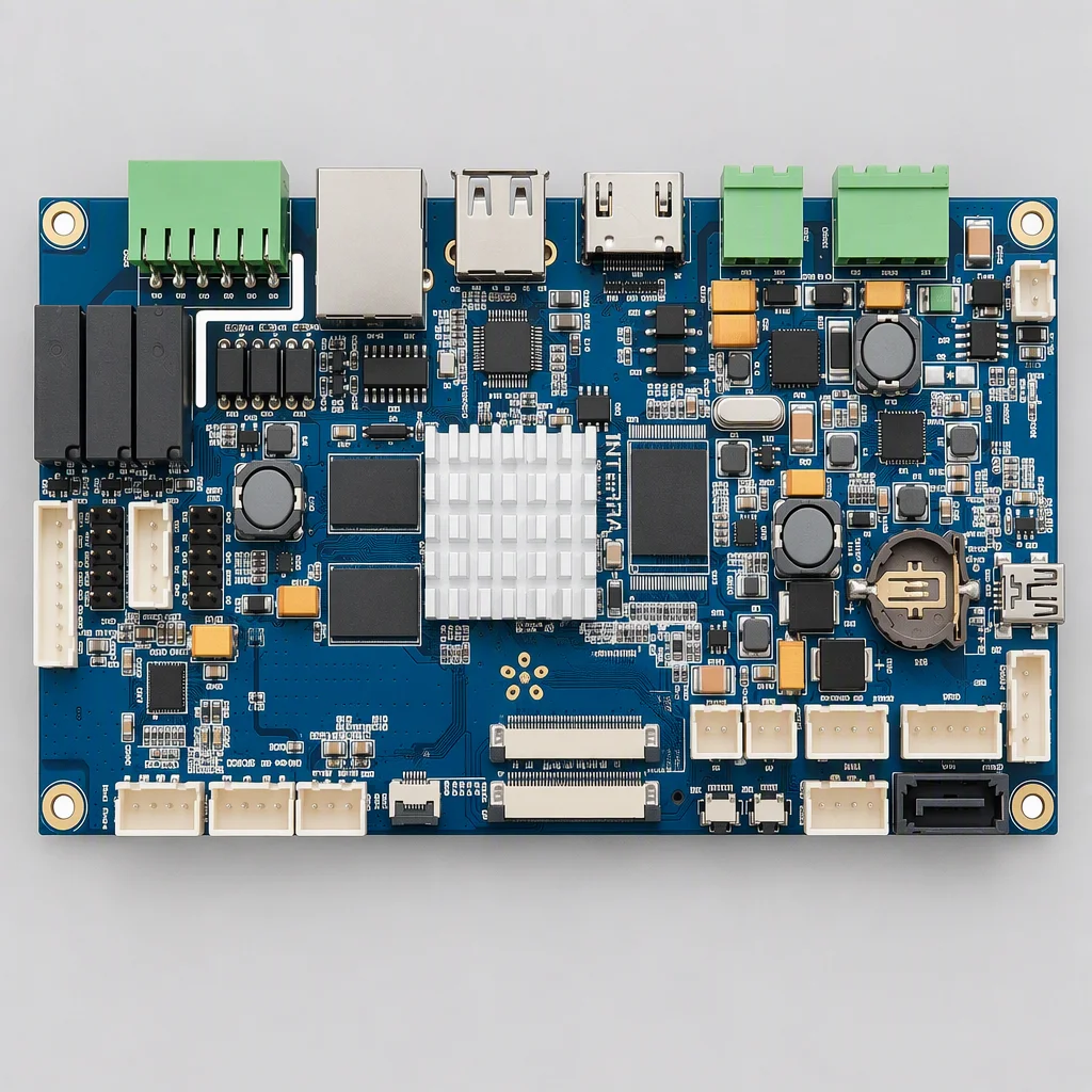
Blue industrial mainboard photographed square on with its heatsink seated along the upper edge and its field-side section partitioned off
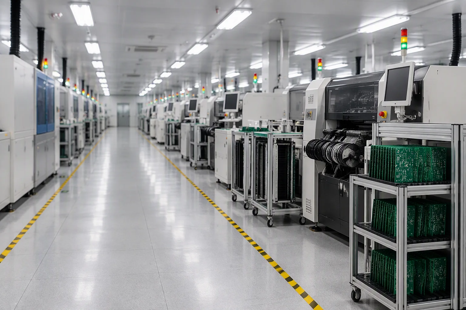
SMT assembly hall aisle with placement machines, feeder carts and green PCB panels stacked on a trolley at the Saturn PCBA plant

Quotation in 24 hours

Send the revision you are locked to and the duty envelope

Gerber, BOM and pick-and-place coordinates, plus the temperature range and expected annual volume if you have them. A DFM report and a price come back within one working day.

[email protected]
Quote in 24 h