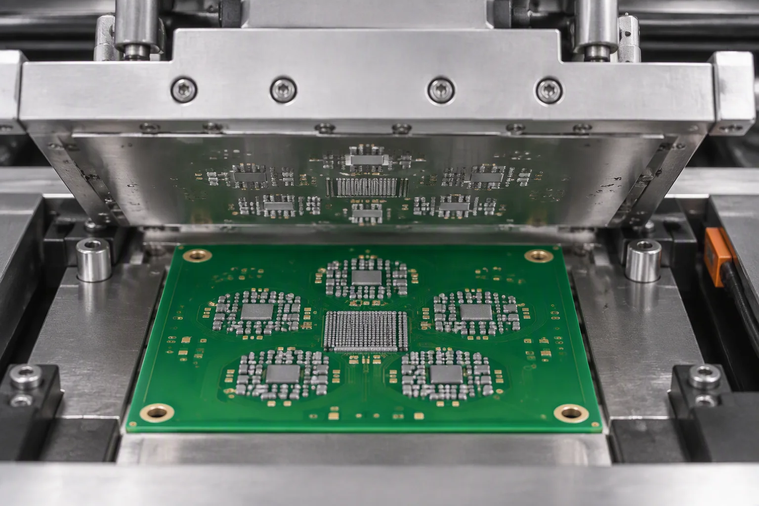
Stencil printing
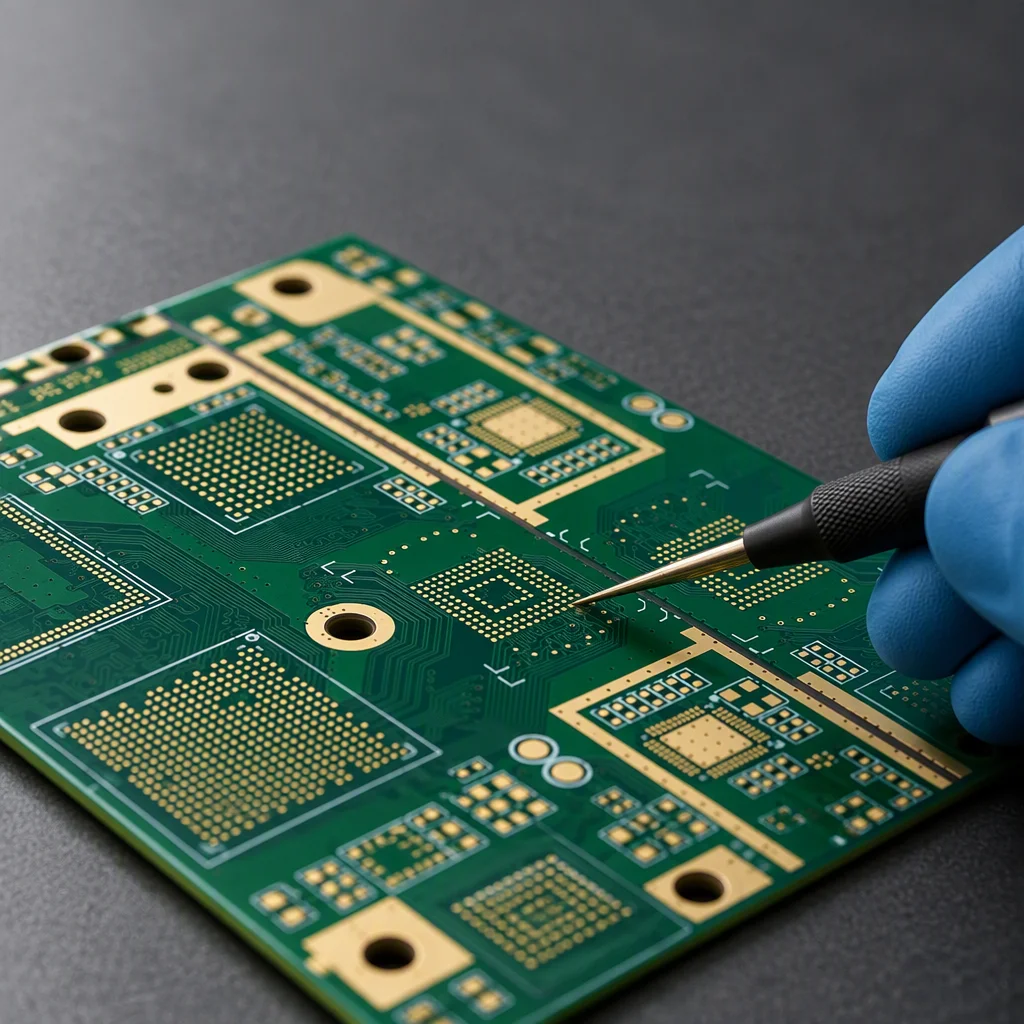
A squeegee drives paste through the apertures; the stencil lifts clean and the deposits stay crisp enough for SPI to measure.
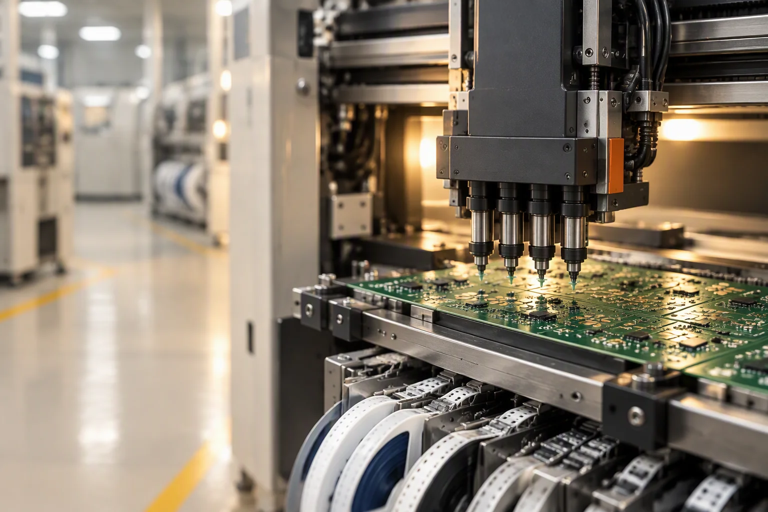
SMT assembly
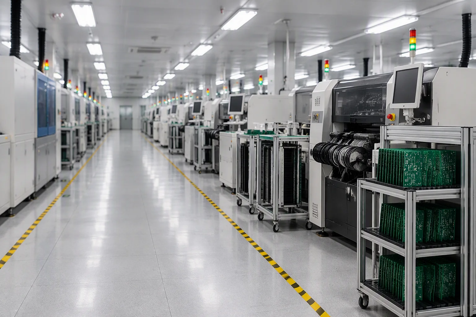
Seven stages, seven checkpoints. 80,000 CPH of placement capability at ±25 µm, 01005 chips and 0.25 mm-pitch BGA, and 3D AOI on 100% of boards across all nine SMT lines.
Seven-stage flow
Every stage below has equipment attached to it and a criterion that decides whether the panel continues. Rework is the seventh stage, not a hidden exception. Aa board that fails AOI or X-ray goes to a named station with a documented disposition.
Printing & SPI
Most assembly defects are decided in the first two stages, before a single component moves. The Koh Young 3D SPI measures four attributes on every printed panel, and a reading outside the window wipes the stencil and reprints before placement starts.
| Item | What is measured or chosen | Why it decides the joint |
|---|---|---|
| Paste volume | Deposited volume per aperture, on every panel | Volume, not pressure, is what forms the fillet, too little and the joint is starved |
| Paste area | Printed footprint against the aperture footprint | Catches a smeared or partially released print that volume alone can hide |
| Paste height | Deposit height above the pad and the mask | Sets how far a 01005 chip has to travel before it touches paste |
| Alignment offset | Deposit position against the pad centre | An offset print becomes a tombstone or a bridge two stages later |
| Stencil | Laser-cut stainless as standard; electroformed for fine-pitch apertures | Aperture wall finish controls paste release on 0.3 mm and finer pitch |
A reading outside the print window does not become a note on a report, it stops the line. The stencil is wiped, the panel is reprinted, and the SPI record for that panel is kept with the work order. Reports can be issued per panel rather than per batch if your quality plan asks for it.
Placement equipment
Rates below are machine placement capability. Real output is a function of component count, panel layout and changeover frequency, so we quote a schedule against your actual board rather than a headline figure.
| Platform or limit | Figure | Where it is used |
|---|---|---|
| ASM SIPLACE X4iS | 80,000 CPH | High-density, high-mix panels. Capability of the machine, not a guaranteed throughput figure |
| Yamaha YSM20R | 72,000 CPH | Flexible changeover and smaller batches, where feeder setup matters more than peak speed |
| Placement precision | ±25 µm | Applied to both platforms, which is what makes 01005 chips and 0.25 mm-pitch BGA workable |
| Component height | ≤25 mm | Above the board surface on the SMT route; taller parts move to the DIP lines |
| Maximum board size on the SMT line | Confirmed per project | Conveyor-class lines typically accept up to 510 × 460 mm. We confirm the window for your panel before release, and it is never assumed |
Reflow
Two convection reflow ovens cover the work: a Heller 1936 MKIII and a BTU Pyramax 125N, both running 8 to 12 zones. Lead-free and leaded pastes are both processed, and the profile for a given assembly is written into the process file rather than dialled in by the operator on the day.
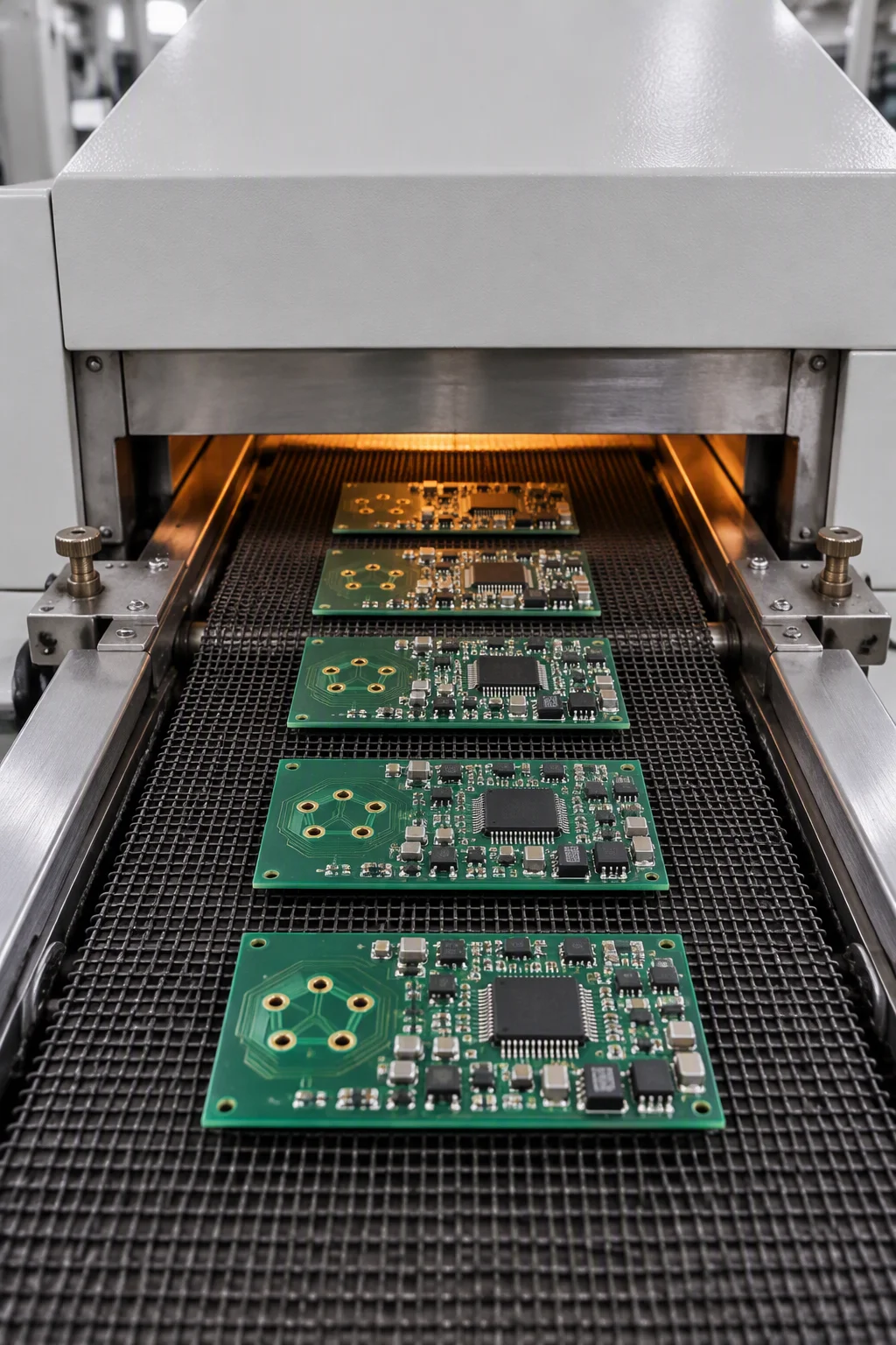
SMT stages on the floor
Printing, placement, optical inspection and X-ray each answer a different question. A board that passes AOI has not been X-rayed, and a board that passes X-ray has not been functionally tested. Which is why the stages run in series, not as alternatives.
A squeegee drives paste through the apertures; the stencil lifts clean and the deposits stay crisp enough for SPI to measure.
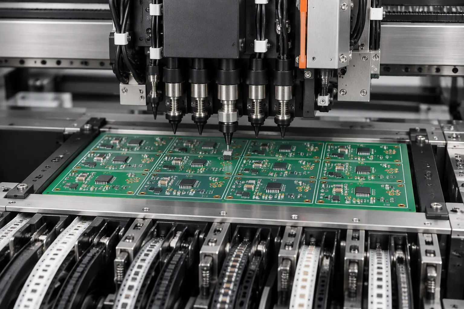
Nozzles pick from reel, tube or tray and place to ±25 µm, tall parts last so nothing is knocked on the way past.
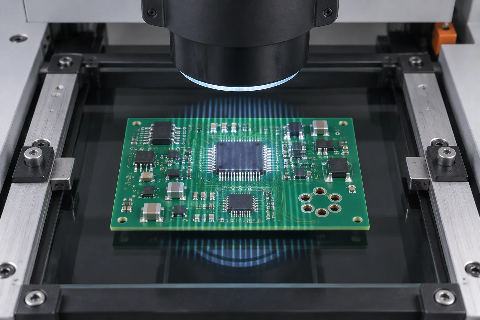
Every board on every line is scanned for missing parts, polarity, offset, tombstoning and joint shape before it leaves the line.
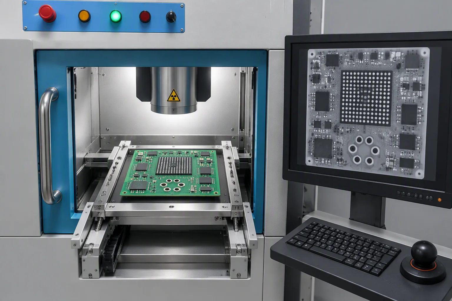
BGA, QFN and LGA joints are imaged from below, with voiding judged to J-STD-001 rather than by eye alone.
Component capability
Before quoting, the package list is checked against the placement window. These are the boundaries that decide whether a design runs on the SMT lines as drawn.
Panelisation & first article
Four gates stand between a Gerber set and a series run. The judgement node is the important one: a first article that misses tolerance goes back to correction instead of forward into production, and the changeover that follows is planned with the same stencil and the same panel.
SMT quotation
Include your panelisation preference if you have one. An engineer checks the package against the placement window and the stencil route, then answers with a price and the first-article plan, within 24 hours.
Send your Gerber, BOM or a plain description. An engineer, not a sales script, reviews it and replies within one working day. NDA on request.