Projects & application cases

Four typical project types, not a logo wall

We do not publish customer names, logos or project numbers. What we can publish is the engineering: the constraint that made each project hard, the process and material route we took, and the inspection evidence that shipped with it.

See the capability range
  • Four project types: industrial control, medical wearable, power and energy, telecom radio
  • Every figure below is a verifiable capability or inspection figure, never a customer result
  • No MOQ, so a 5-piece validation build and a 50,000-piece series use the same nine lines

Case 1 & case 2

Long-life control boards, and a board that bends

Two projects that pull in opposite directions: one has to survive for a decade in an enclosure, the other has to survive being worn.

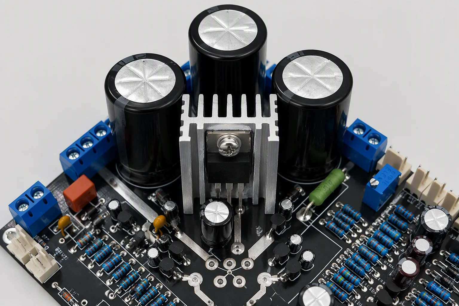
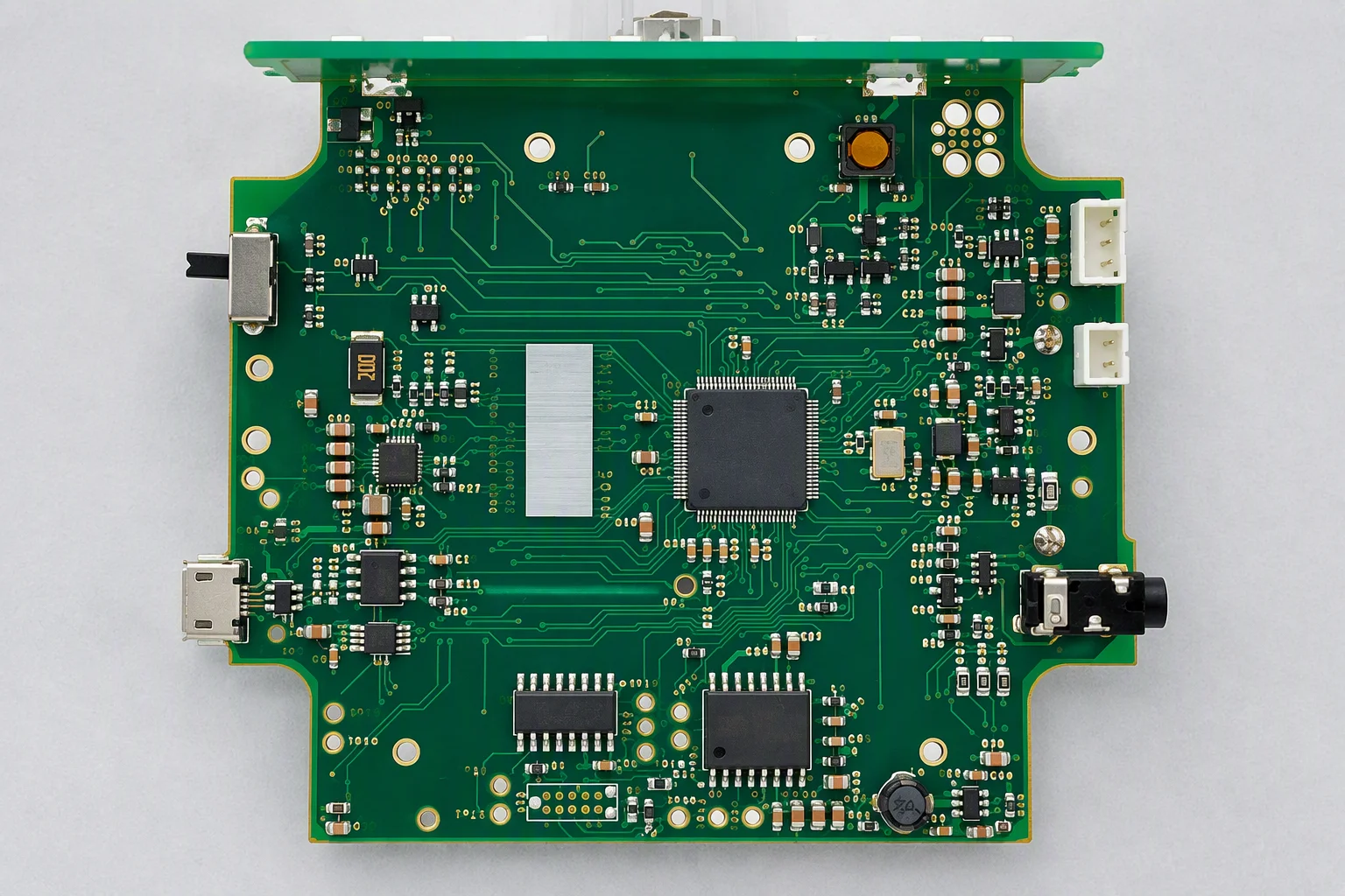
Six-layer industrial control mainboard with gold edge fingers, isolated power zone and through-hole connectors

Industrial control & automation

A control mainboard built for a 10-15 year service life

Requirement
The unit runs in a cabinet for 10-15 years with a -40 to +85 °C ambient window, a 24 V supply that must stay isolated from the logic domain, and an edge connector that is plugged and unplugged during commissioning and service.
Solution
A 6-layer High-Tg stack with Tg of 170 °C or above, which lead-free reflow effectively demands; 2 oz inner copper for the power planes; ground-plane partitioning to keep the 24 V domain away from the analogue front end; impedance held at ±5% and verified by a TDR coupon on the board edge; and life-cycle BOM management with documented alternates for parts facing end of life.
Outcome
Gold-finger edge plating rated for more than 10,000 mating cycles, soldermask and legend inside the 0.1 mm dam and 0.15 mm legend limits, and a documentation trail that closes each alternate part with a written customer approval.
6 layers · High-Tg 170 °C+ · 2 oz inner copper
Impedance ±5% with a TDR coupon record
100% AOI · X-ray minimum 5 per batch · OQC to AQL Z1.4
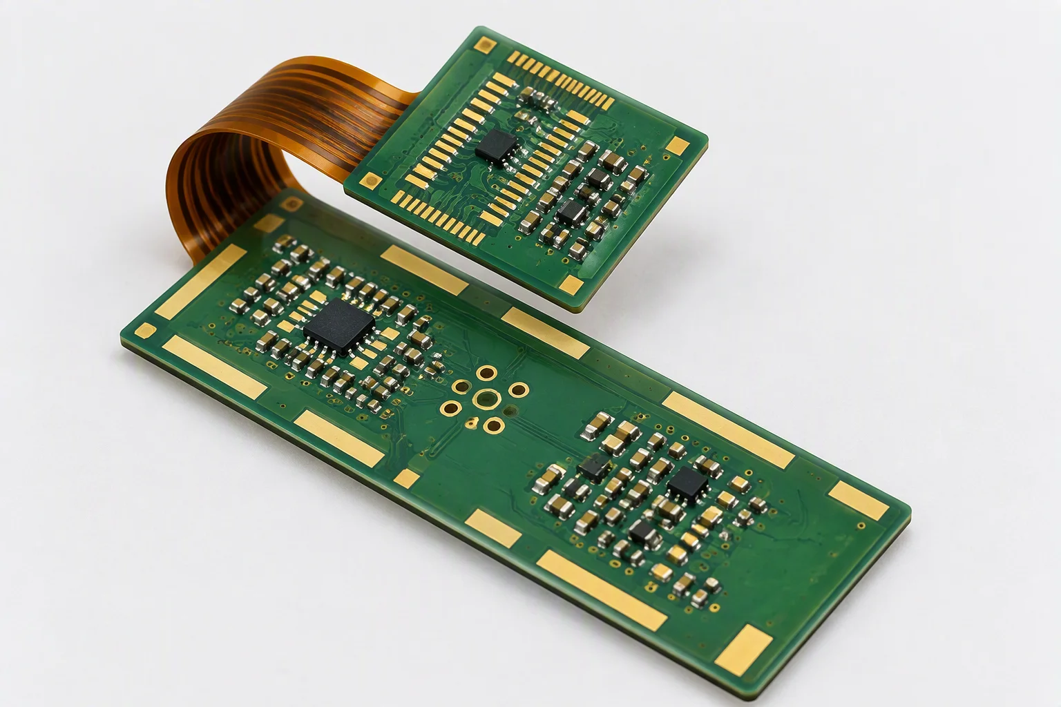
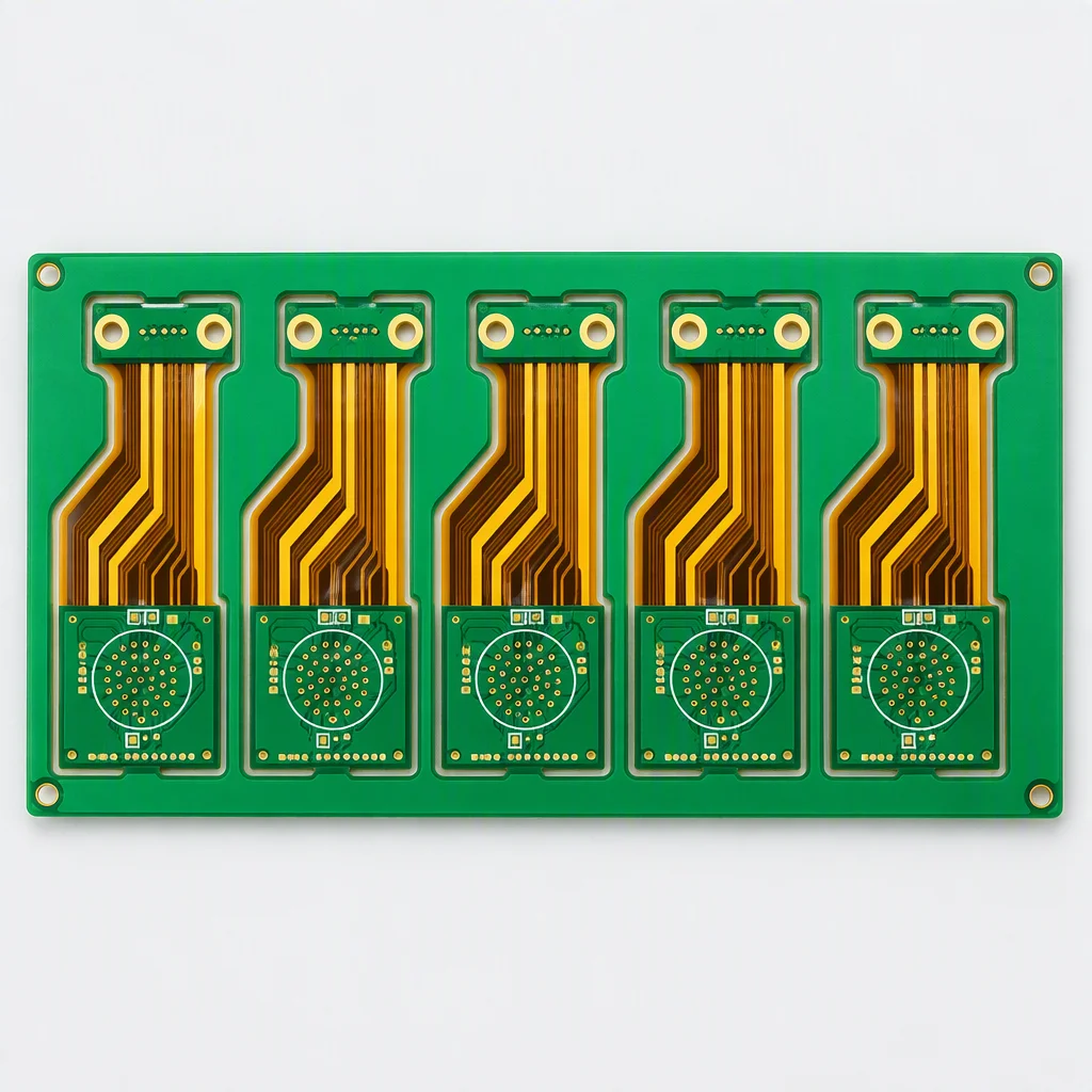
Polyimide rigid-flex wearable board with a stiffener, fine-pitch components and a coating over the assembly

Medical devices & wearables

Rigid-flex wearable where every unit must be traceable

Requirement
A wrist-worn assembly that has to survive a bending envelope measured in tens of thousands of cycles, carry an 01005 component population next to a fine-pitch package, and prove after the fact which component lot went into which unit.
Solution
A polyimide rigid-flex construction with stiffeners under the connector and the display area; 01005 passives placed alongside BGA down to 0.25 mm pitch on the same panel; selective conformal coating in silicone or polyurethane at 25-210 µm by chemistry, to IPC-CC-830B; ultrasonic plus DI-water cleaning before coating; and a custom FCT fixture developed jointly with the customer's engineering team.
Outcome
A serial number on every unit that resolves to one panel position, one work order and one production date, with final visual inspection photographs archived per batch and a CoC plus test report in the carton. Medical-grade process capability is documented through serialisation and full traceability rather than asserted as a certificate.
Serialised units · archived FVI photographs
100% AOI · X-ray minimum 5 per batch to J-STD-001
ICT 3,072 points or flying probe, 4 heads

Case 3 & case 4

A hundred amps through copper, and a stable impedance

The other two directions: heavy copper that has to carry current and shed heat, and a radio board where a fraction of an ohm decides whether the specification is met.

Heavy-copper power board with wide tinned busbars, a metal-core section and large exposed copper planes

Power & energy storage

4-20 oz copper for a 100 A class power path

Requirement
A converter stage carrying a 100 A class current, a metal-core section that has to move heat out of the switching devices, a high-voltage domain that needs creepage and clearance of its own, and a field environment where condensation is a real event.
Solution
A heavy-copper board at 4-20 oz on the power layers, with an aluminium IMS section zoned against the FR-4 logic area on the same assembly; High-Tg laminate at 170 °C or above so the stack survives lead-free reflow; selective conformal coating in silicone or polyurethane for the high-voltage side; and epoxy potting where the customer's enclosure calls for it. Panel size is planned against the 600 × 1200 mm maximum.
Outcome
Copper thickness verified against the released stackup with test records retained per batch, the flying-probe programme covering every net on all 4 heads, and shipment documentation that includes the coating chemistry and thickness range applied to the assembly.
4-20 oz heavy copper · aluminium IMS zoning
Boards to 600 × 1200 mm · potting on request
100% AOI · flying probe 4 heads · AQL Z1.4 at OQC
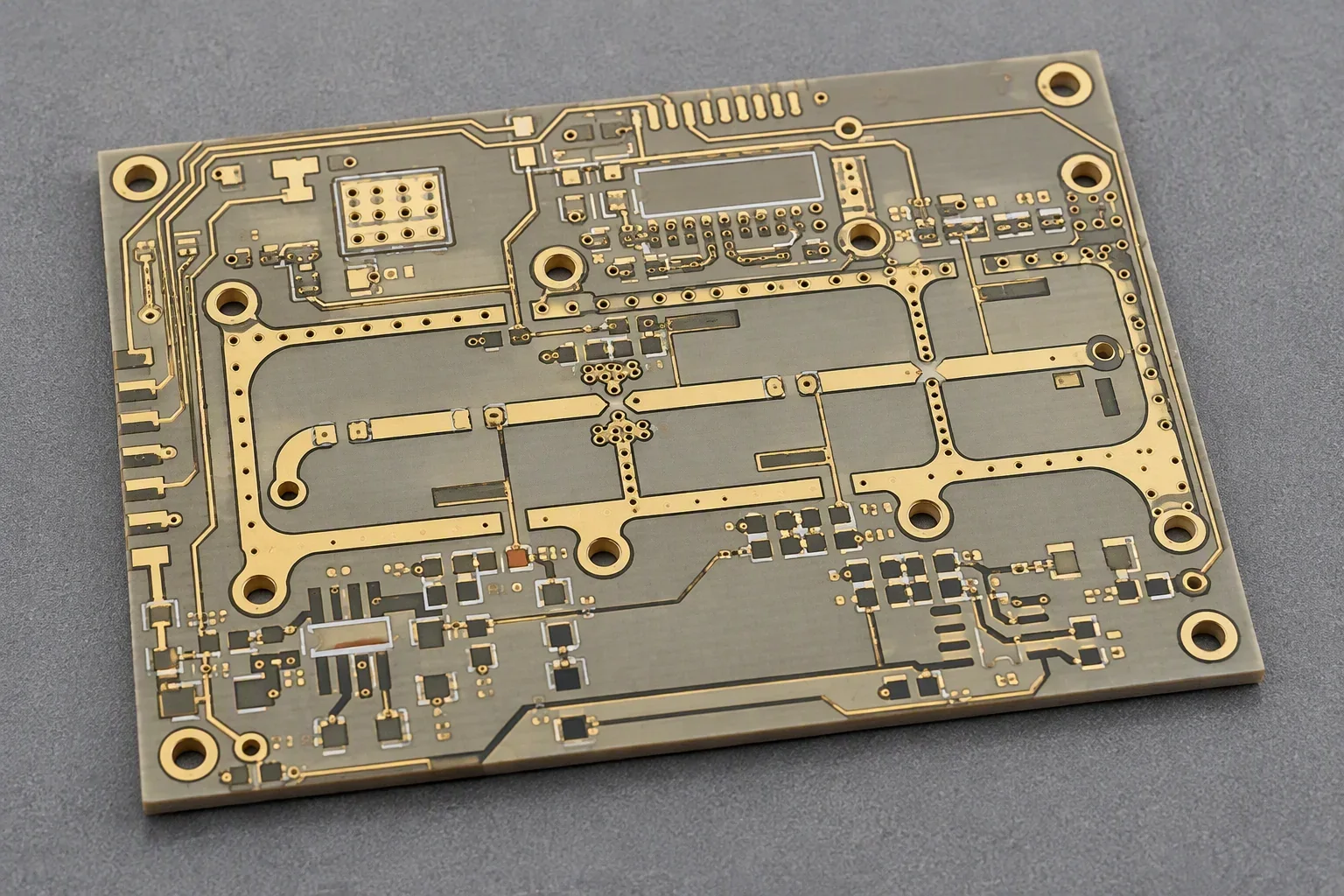
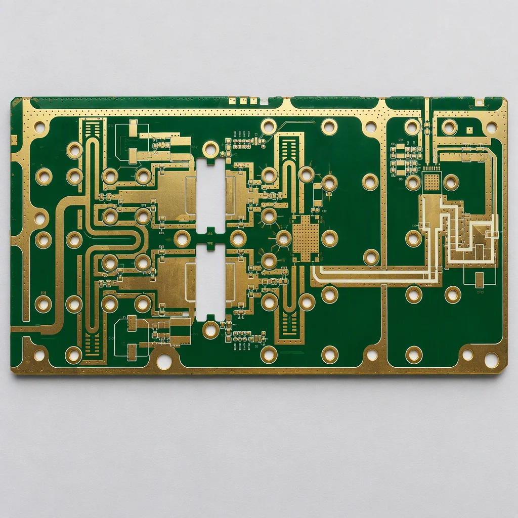
Radio frequency board with a milled antenna array, coplanar transmission lines and a press-fit connector footprint

Telecom & networking

An 8.6-9.6 GHz front end that cannot drift

Requirement
A power-amplifier front end operating in the 8.6-9.6 GHz band, where insertion loss and impedance stability decide the link budget; a four-element microstrip antenna array that needs large copper areas held coplanar; and press-fit connectors that have to seat identically across a whole batch.
Solution
A hybrid stack that mixes low-loss laminate with FR-4 so the radio layers get the dielectric they need without paying for the whole board; 2.5 mil line and space on the HDI layers with 0.1 mm laser microvias into the ground planes; impedance held at ±5% and verified by a TDR test strip on the board edge; and a controlled coplanarity window across the antenna copper.
Outcome
A TDR report that travels with each batch, an ICT programme at 3,072 points behind a custom FCT fixture that exercises the radio chain, and press-fit assembly verified at final visual inspection to IPC-A-610 Class 2 with Class 3 available where the build class requires it.
Low-loss laminate hybrid · ±5% impedance with TDR
2.5 mil line and space · 0.1 mm laser microvias
ICT 3,072 points · FCT fixture built with your engineers

Route comparison

The project types, side by side on the columns that differ

The same four projects as a matrix, plus the production route each one took. Use the column that matters to you as the coordinate for your own build.

Four project types × six comparison columns
Industry Layers & thickness Copper Material & finish Key inspection Delivery scope
Industrial control 6 layers, High-Tg, inside the 0.4-3.2 mm range 2 oz inner layers FR-4 High-Tg 170 °C+, ENIG or hard gold on the edge fingers 3D AOI 100%, X-ray min 5 per batch, ICT 3,072 points PCB plus turnkey assembly, box build on request
Medical wearable Rigid-flex, polyimide, stiffener at the connector 1 oz with 0.1 mm laser microvias where needed Polyimide FPC, ENIG to IPC-4552, selective coating 25-210 µm Serial traceability, FVI photographs to IPC-A-610 Class 2 or 3 Turnkey assembly with serialisation and CoC
Power & energy Heavy copper, aluminium IMS zoned against FR-4 4-20 oz on the power layers High-Tg FR-4 plus IMS, HASL lead-free or ENIG Flying probe 4 heads on every net, X-ray min 5 per batch PCB, assembly, selective coating and potting
Telecom & radio 8-20+ layers, low-loss hybrid stackup 1-2 oz with 2.5 mil line and space Rogers-class low-loss laminate, ENIG for fine pitch TDR impedance report per batch, ICT 3,072 points, FCT PCB, SMT and press-fit assembly, test development

Plate gallery

The four boards, same light, same distance

One dense SMT plate, one five-up rigid-flex panel, one heavy-copper plate and one four-element antenna array.

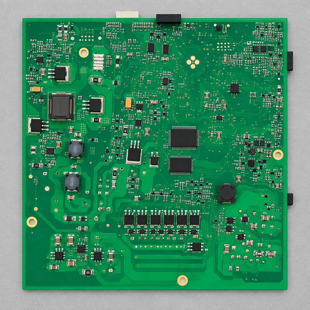
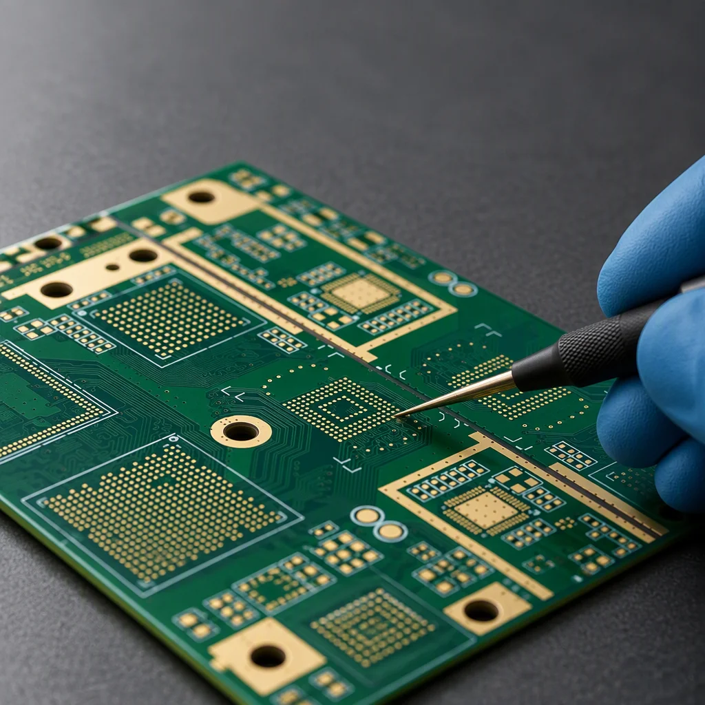
Densely populated green SMT board with fine-pitch packages and 01005 passives under even studio light

High-density SMT

01005 passives and BGA to 0.25 mm pitch on one plate.

Five-up rigid-flex panel with polyimide flex sections joined to rigid islands by breakaway tabs

Rigid-flex panel

Five circuits per panel with stiffeners and tabs.

Bare heavy-copper board with wide exposed copper planes and a gold-plated busbar area

Heavy copper, bare board

4-20 oz power layers before assembly.

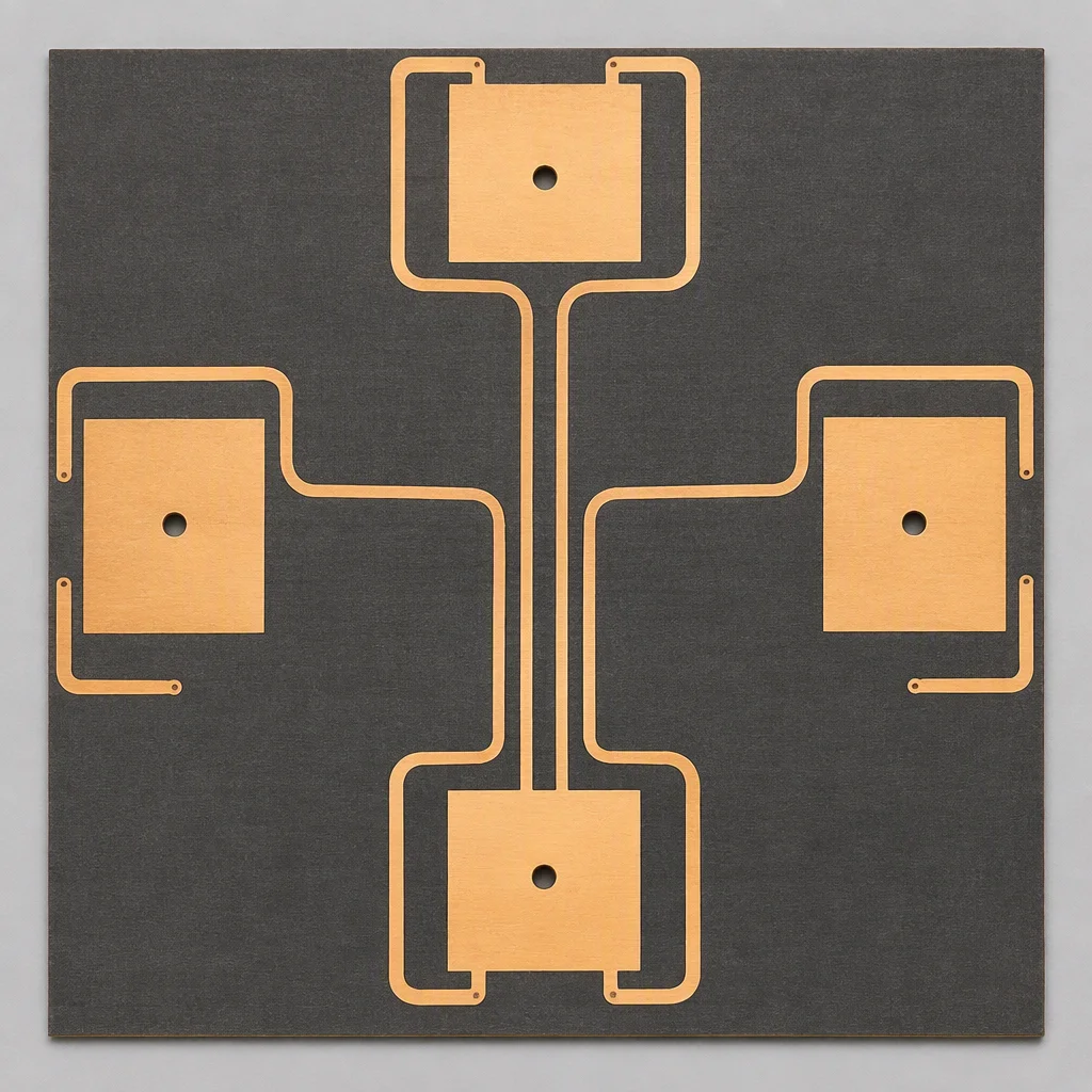
Four-element microstrip antenna array with large coplanar copper areas on a low-loss laminate

Microstrip antenna array

Four elements, coplanarity held across the copper.

Capability mapping

Which part of the plant your project goes through

Six production modules, each with the equipment or standard that decides whether your design fits it.

PCB fabrication

1-58 layers in-house, 2-8 layers as the volume tier, 2.5 mil line and space on HDI, 0.2 mm mechanical and 0.1 mm laser drilling.

SMT assembly

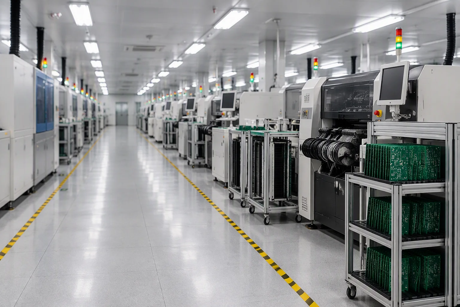
Nine lines, placement accuracy ±25 µm, 01005 to BGA at 0.25 mm pitch, 3D SPI before placement and 3D AOI after reflow.

DIP, wave and selective solder

4-5 DIP lines, wave soldering on fixtured pallets, programmable selective soldering for mixed-technology boards, hand soldering to IPC-A-610.

Test and inspection

X-ray to J-STD-001, flying probe with 4 heads, ICT at 3,072 points, FCT on a custom fixture, OQC to AQL ANSI/ASQ Z1.4 (general inspection level II, single sampling, normal severity, AQL 0.65 for major defects).

Coating and potting

Acrylic 25-75 µm, silicone 50-210 µm, polyurethane 25-75 µm, epoxy 25-125 µm or parylene 5-50 µm, to IPC-CC-830B.

Box build, harness and sheet metal

Wiring, sheet-metal parts and final pack-out, so a turnkey order leaves as a boxed unit rather than a bag of boards.

Quotation in 24 hours

Tell us which project type you are building

Name your case, industrial, medical, power, telecom or something else, and an engineer will route it to the right line and reply with a quotation and a DFM report.

[email protected]
Quote in 24 h