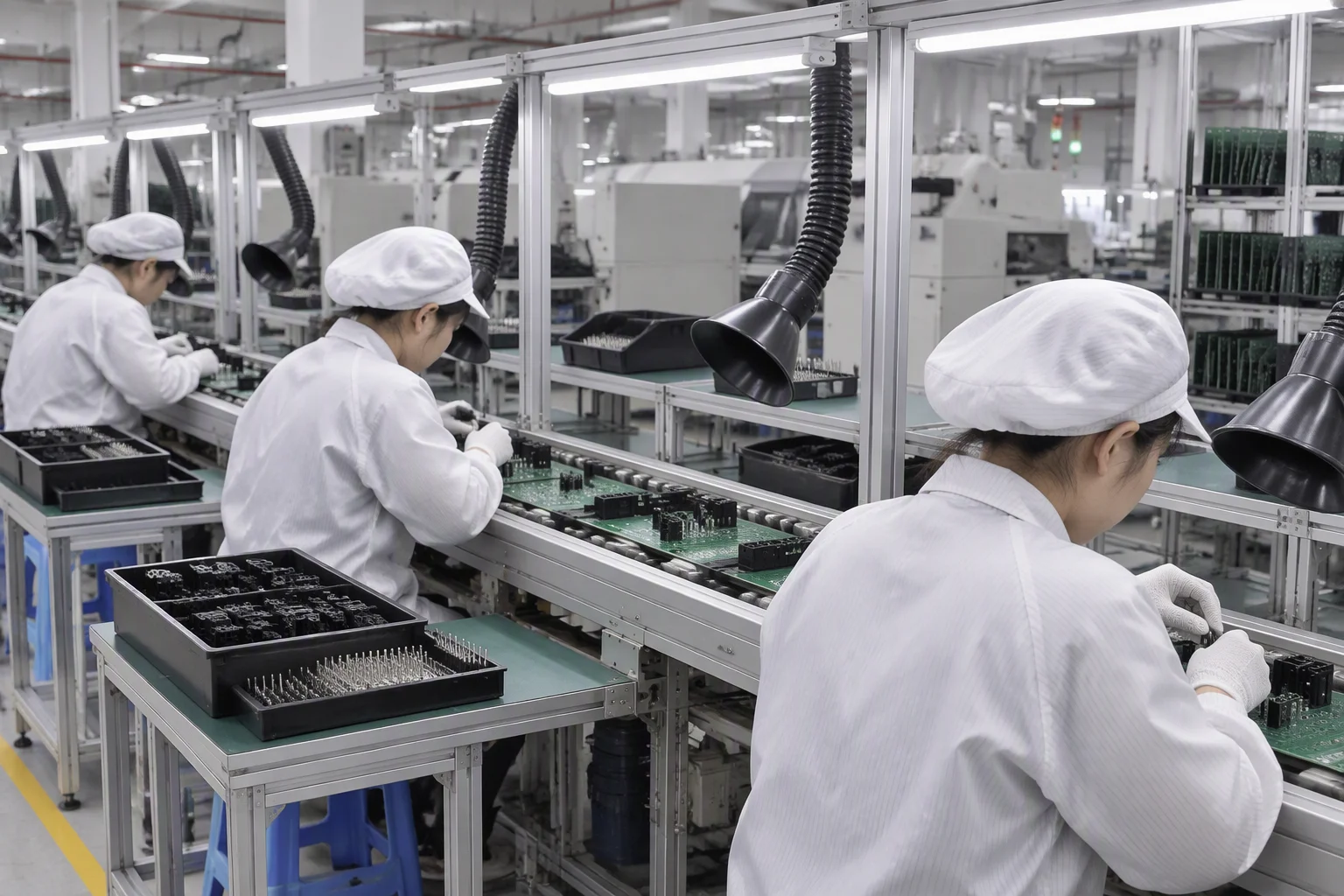
Insertion line
Components are seated by hand along the belt, with polarity and lead protrusion checked before the board reaches the wave.
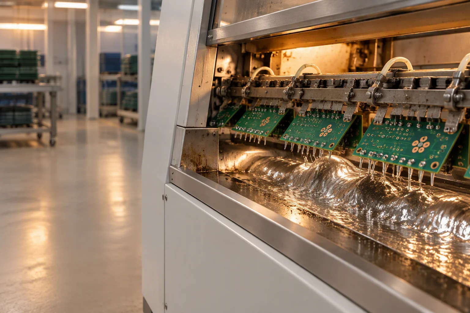
Through-hole & DIP
Four to five dedicated DIP lines carry through-hole, wave, programmable selective, hand soldering and press-fit work. Every parameter is recorded per batch, and every joint is judged against IPC-A-610 Class 2 or Class 3.
DIP line flow
Through-hole work is a sequence of physical operations, and each one has a condition that has to hold before the board moves on. Insertion is judged on lead placement, the wave on fill, touch-up on workmanship, cleaning on residue, and inspection against the class your drawing names.
Wave parameters
A wave solder machine has six settings that matter, and all six are written into the process file for the assembly rather than left to the operator. The sheet travels with the work order, so any board can be traced back to the settings it was soldered under.
| Parameter group | What the setting controls | How it is recorded |
|---|---|---|
| Flux application | Flux type and the amount deposited on the underside before the wave | Process file, checked at setup, logged per batch |
| Pre-heat | Zone temperatures that bring board and flux up to temperature before contact | Process file, checked at setup, logged per batch |
| Solder pot and wave | Pot temperature and wave height for the alloy in use | Process file, checked at setup, logged per batch |
| Conveyor speed | Contact time between the joint and the wave, and therefore fill | Process file, checked at setup, logged per batch |
| Post-solder cooling | Cooling rate after the wave, so joints and laminate are not thermally shocked | Process file, checked at setup, logged per batch |
| Line capacity | Four to five dedicated DIP lines, separate from the nine SMT lines | Work-order routing |
The correct pot temperature, pre-heat profile and conveyor speed depend on board thickness, copper weight, thermal mass and the alloy in use, so a single published figure would be wrong for most assemblies. What we commit to is the method: every value is set from the process file for your board, confirmed at setup, and recorded against the work order so the batch can be traced and repeated exactly. The numbers themselves are confirmed per project during engineering review.
Process choice
A mixed-technology board usually cannot cross a full wave without putting its surface-mount side at risk. Selective soldering exists for exactly that case: a single nozzle heats one joint or one row, and nothing else on the panel is disturbed.
| Parameter | Wave soldering | Programmable selective soldering |
|---|---|---|
| Equipment | The DIP line's wave machine, running the full panel across the crest | Seho ECOSyS 3000 and ERSA Versaflow 3 stations |
| Board types | Through-hole boards, and mixed boards whose underside can be masked | Mixed-technology boards where only a few joints may be heated at all |
| Heat input | The whole underside crosses the wave in one pass | One nozzle or mini-wave, positioned joint by joint from the programme |
| Through-hole fill | Fill is consistent across the panel when barrels and thermal relief are designed for it | Fill is set per joint in the programme, which is what makes a single tall connector repeatable |
| Neighbouring parts | Bottom-side SMT parts have to be masked or glued before the board crosses | SMT parts up to 25 mm tall can sit beside the joint and stay untouched |
| Choose it when | The assembly is mostly through-hole and the volume is steady | Only a few joints need solder, or heat-sensitive parts sit close to them |
Selective soldering
Selective soldering is programmed from the same coordinate data used for placement, so each joint gets its own approach, dwell and wave height. That is what makes it repeatable on a board where a connector sits a few millimetres from a part that cannot see reflow temperatures twice.
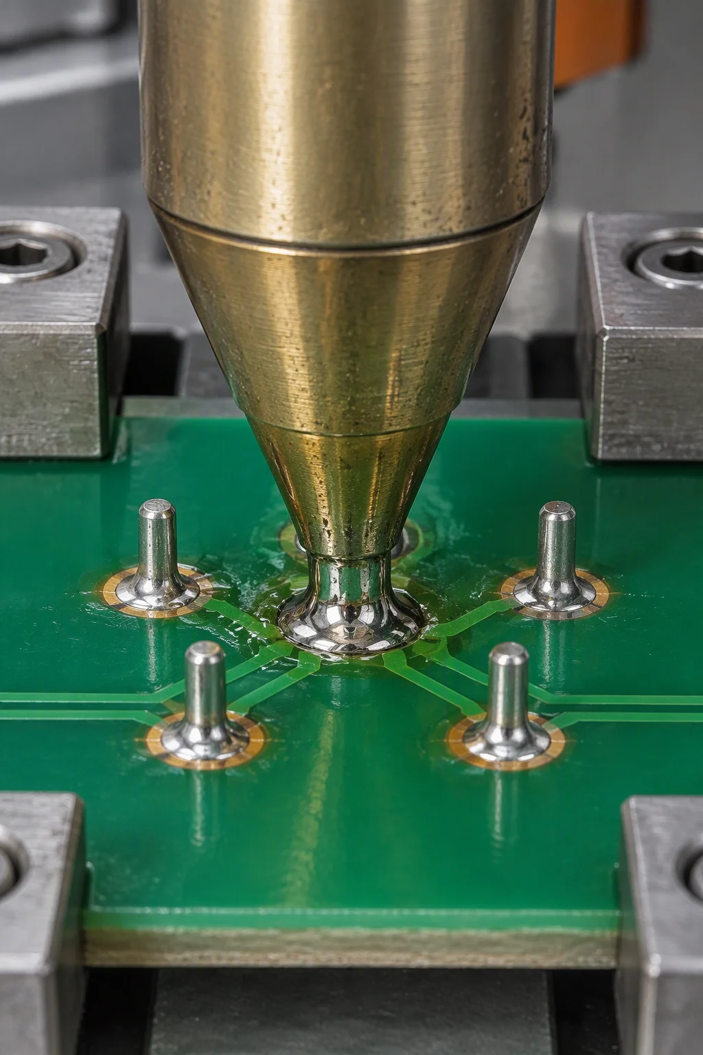
Hand soldering & press-fit
Hand work is where a process quietly becomes an opinion, so the acceptance criteria are written down rather than inherited. Every manual joint is judged against the same documents the wave and selective stations are judged against.
The DIP zone
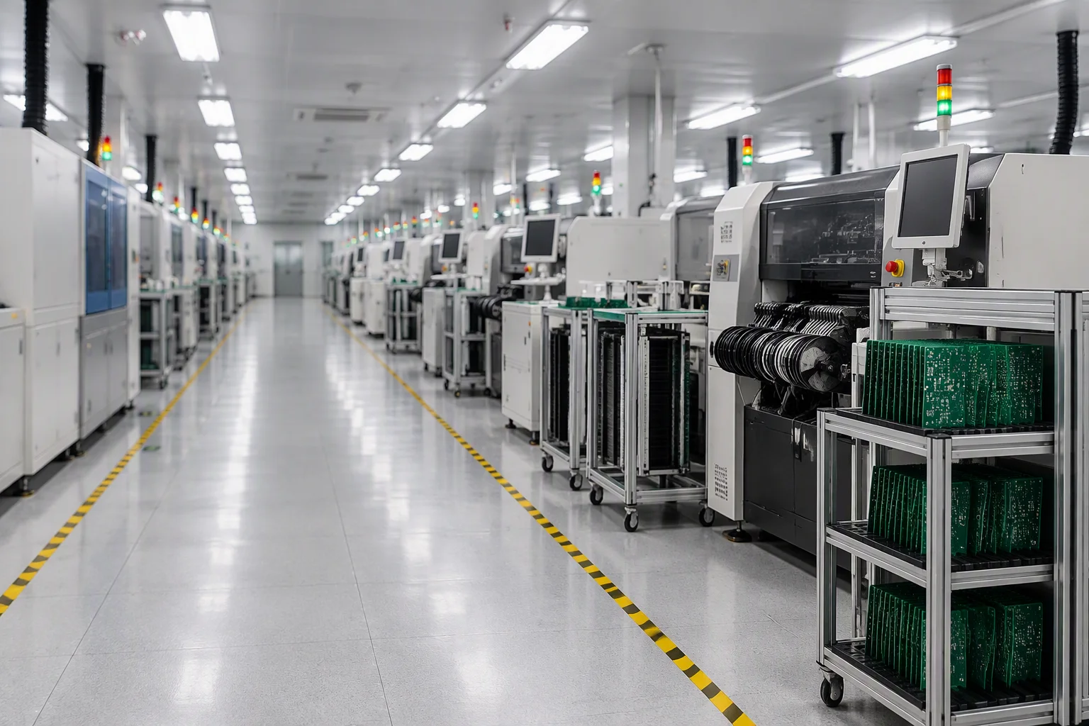
Insertion, soldering, touch-up and cleaning are separate physical stations with their own equipment and their own records. Seeing them side by side is the quickest way to judge whether a plant actually runs through-hole work or subcontracts it.
Components are seated by hand along the belt, with polarity and lead protrusion checked before the board reaches the wave.
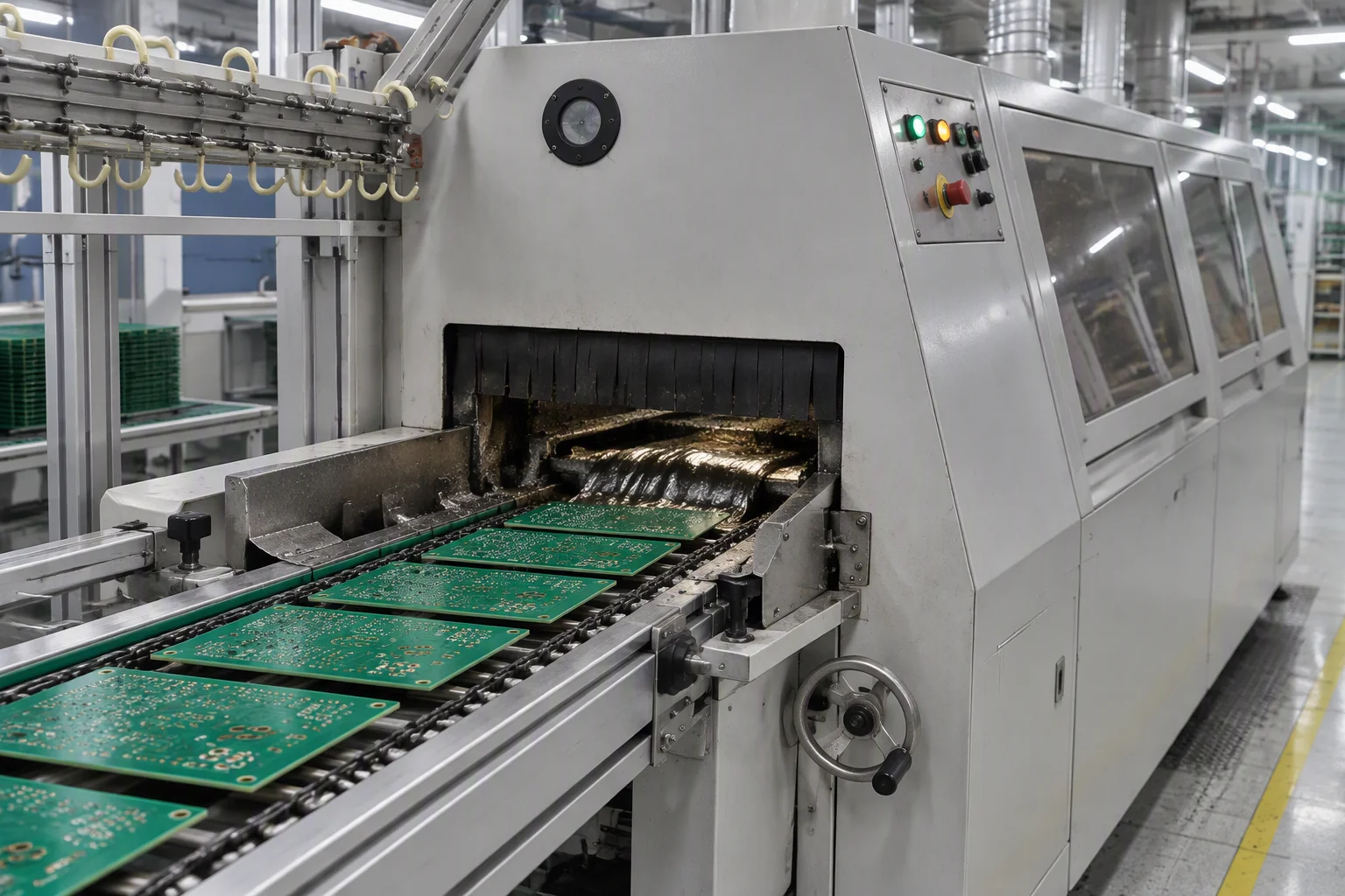
Flux, pre-heat, pot and wave settings run from the process file, and the settings sheet is signed off against the batch.
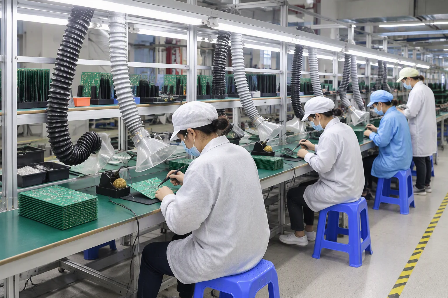
Manual joints and any joint flagged at inspection are corrected here, to the class named on the assembly drawing.
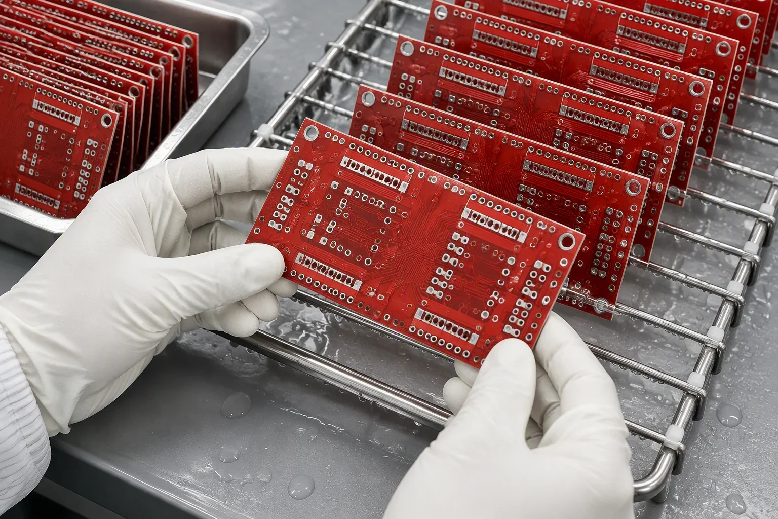
Boards come out of the ultrasonic and DI-water clean, are dried, then move to final inspection or on to box build.
Rework & repair policy
The four answers below are the ones buyers ask for before they release a through-hole build. They describe the boundary between repair, scrap and a documented corrective action, not a promise about how often any of them happens.
Against IPC-A-610 Class 2 or Class 3, with the soldering requirements of J-STD-001 behind it. The class is the one named on your assembly drawing, and it is applied to wave joints and hand joints alike.
Repair is for joints. Laminate damage, a lifted pad, a cracked barrel or damage to an inner-layer connection is not a soldering defect, and reworking it would only move the failure somewhere less visible.
An 8D report with a corrective and preventive action, taken at the monthly quality review. The action is written against the process step that produced the defect, pre-heat, flux, conveyor speed or insertion, rather than against the operator.
Consignment material stays the buyer's property. When a supplied part fails, the finding is reported with photographs, the production date code and the lot record so a claim can be raised with the original distributor.
Through-hole quotation
Component heights, connector types and the class your drawing names are what decide whether a board runs over the wave or through a selective nozzle. Send them with the BOM and an engineer answers within 24 hours.
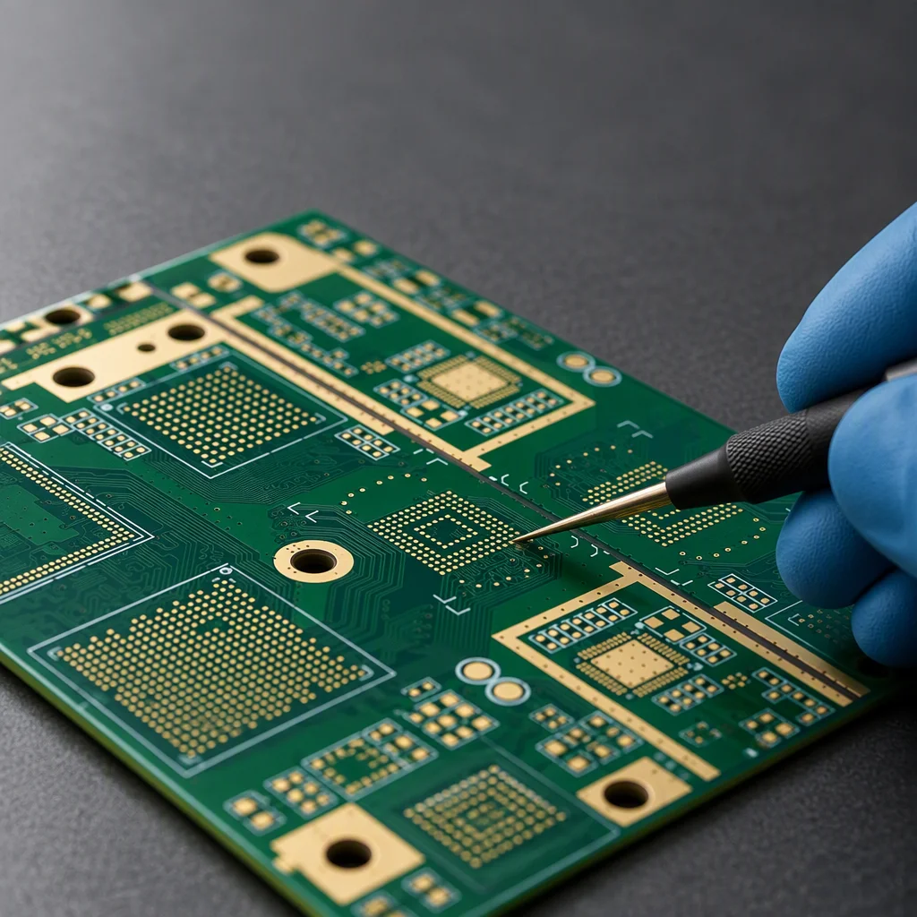
Send your Gerber, BOM or a plain description. An engineer, not a sales script, reviews it and replies within one working day. NDA on request.